Low temperature co-fired ceramic material, low temperature co-fired ceramic body, and multilayer ceramic substrate

a co-fired ceramic and low temperature technology, applied in the direction of metallic pattern materials, solid-state devices, record information storage, etc., can solve the problem of easy sinterability and quality variation between raw material lots

Active Publication Date: 2012-07-31
MURATA MFG CO LTD
View PDF22 Cites 4 Cited by
  • Summary
  • Abstract
  • Description
  • Claims
  • Application Information

AI Technical Summary

Benefits of technology

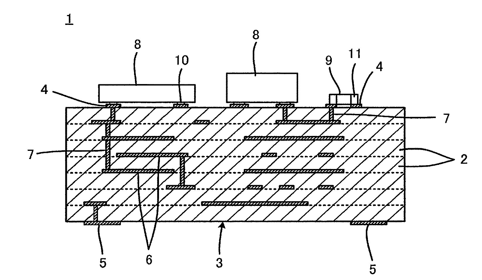
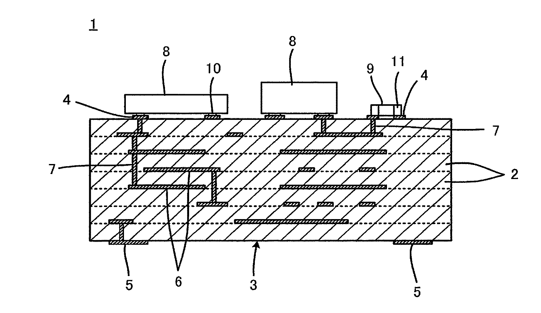
[0008]It is an object of the present invention to provide a low temperature co-fired ceramic material that can solve the problem described above, a low temperature co-fired ceramic body obtained by sintering the low temperature co-fired ceramic material, and a multilayer ceramic substrate manufactured using the low temperature co-fired ceramic material.
[0014]In the low temperature co-fired ceramic material according to preferred embodiments of the present invention, predetermined amounts of iron and zirconium, as secondary components which serve as sintering aids, are added to the SiO2—BaO—Al2O3-based primary component, and the amounts of iron and zirconium are strictly controlled. As a result, the multilayer ceramic substrate constituted by using the low temperature co-fired ceramic body formed by sintering the low temperature co-fired ceramic material can have advantages, such as high dimensional accuracy, good plating adhesion, high bond strength of the surface conductor film to the substrate, high strength (flexural strength or bending strength) of the substrate itself, small warpage and waviness, and high substrate density (good electrical properties).
[0015]In particular, when the SiO2—BaO—Al2O3-based primary component has a composition including 47% to 60% by weight of SiO2, 20% to 42% by weight of BaO, and 5% to 30% by weight of Al2O3, the advantages described above can be more satisfactorily and reliably attained.

Problems solved by technology

However, the SiO2—BaO—Al2O3-based low temperature co-fired ceramic material has a problem in that, in particular, when multilayer ceramic substrates are industrially manufactured using this ceramic material as a raw material, a variation in quality (in particular, sinterability) easily occurs between raw material lots.

Method used


Image

  • Low temperature co-fired ceramic material, low temperature co-fired ceramic body, and multilayer ceramic substrate
  • Low temperature co-fired ceramic material, low temperature co-fired ceramic body, and multilayer ceramic substrate

Examples


experimental example 1

[0048]First, as starting material powders for the primary component of a low temperature co-fired ceramic material, SiO2, BaCO3, and Al2O3 powders, each having an average particle size (D50) of 2.0 μm or less, were prepared. Next, the starting material powders were weighed so as to satisfy the compositions shown under the column titled “Primary component” in Table 1. Furthermore, Fe2O3 as the secondary component was made to adhere to the surface of the SiO2 powder in advance so as to satisfy the amount shown under the column titled “Additive component” in Table 1.

[0049]Next, a mixed powder obtained by mixing the starting material powders was calcined at a temperature of 800° C. to 1,000° C. The resulting calcine was pulverized, and during the pulverization, a ZrO2 powder was added thereto in the amount shown under the column titled “Additive component” in Table 1. Thereby, a low temperature co-fired ceramic material powder for each sample was obtained.

[0050]In Table 1, SiO2, BaCO3, ...


PUM

PropertyMeasurementUnit
temperatureaaaaaaaaaa
pressureaaaaaaaaaa
melting pointaaaaaaaaaa

Abstract

A low temperature co-fired ceramic material includes a SiO2—BaO—Al2O3-based primary component, and, as secondary components, 0.044 to 0.077 parts by weight of iron in terms of Fe2O3 and 0.30 to 0.55 parts by weight of zirconium in terms of ZrO2 relative to 100 parts by weight of the SiO2—BaO—Al2O3-based primary component. The SiO2—BaO—Al2O3-based primary component preferably includes 47% to 60% by weight of SiO2, 20% to 42% by weight of BaO, and 5% to 30% by weight of Al2O3.

Description

BACKGROUND OF THE INVENTION[0001]1. Field of the Invention[0002]The present invention relates to a low temperature co-fired ceramic material, a low temperature co-fired ceramic body, and a multilayer ceramic substrate. More particularly, the invention relates to improvements for suppressing variation in sinterability of a low temperature co-fired ceramic material.[0003]2. Description of the Related Art[0004]A SiO2—BaO—Al2O3-based low temperature co-fired ceramic material is known as an electrical insulation material used for multilayer ceramic substrates. This material can be co-fired with a metal material that has low resistivity, such as copper, and has high insulation resistance and a low dielectric constant, thus being useful, in particular, as a substrate material used for electronic component modules for radio frequency applications.[0005]In order to improve various properties, additives are added to the SiO2—BaO—Al2O3-based low temperature co-fired ceramic material. For examp...

Claims


Application Information

Patent Timeline
Patent Type & Authority Patents(United States)
IPC IPC(8): H05K1/09
CPCB32B18/00C04B35/6262C04B35/62685H05K3/4629C04B35/195Y10T428/24926C04B2235/3215C04B2235/3244C04B2235/3272C04B2235/5436C04B2235/6025C04B2235/656C04B2235/77C04B2235/96C04B2237/341C04B2237/66C04B2237/704H01L23/15H01L2224/16225H01L2924/15192H01L2924/19105Y10T428/24355
Inventor YOKOYAMA, TOMOYAKAWADA, YUZOBABA, AKIRAKAWAKAMI, HIROMICHIKATO, ISAO
Owner MURATA MFG CO LTD
Why Eureka
Try Eureka