Fodder-growing enclosure

a technology of growing enclosure and fodder, which is applied in the field of production of fodder, can solve the problems of uneven growth of fodder, difficult manipulation of trays of fodder, and systemic manipulation of trays, and achieve the effect of convenient sliding of trays and convenient mat removal

Inactive Publication Date: 2012-08-07
COLLESS TERRY +1
View PDF15 Cites 58 Cited by
  • Summary
  • Abstract
  • Description
  • Claims
  • Application Information

AI Technical Summary

Benefits of technology

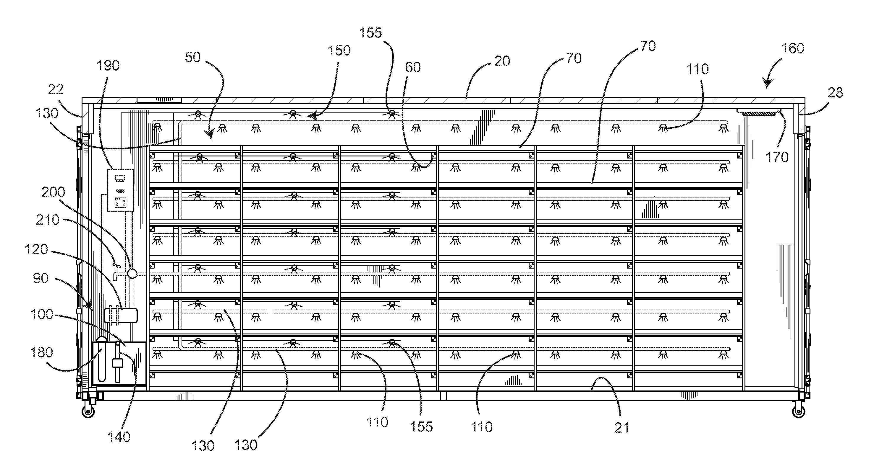
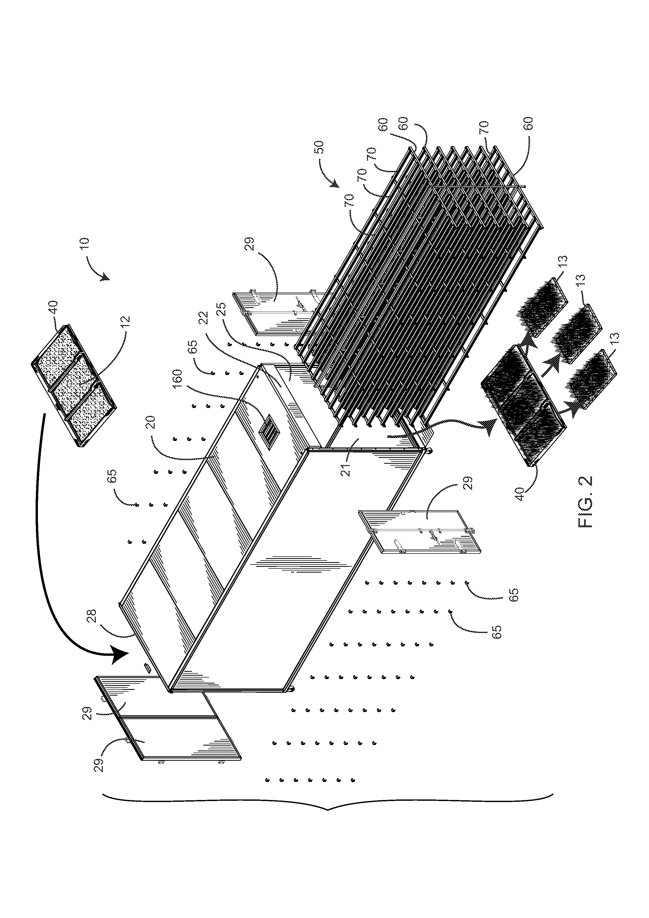
[0013]A plurality of trays are included, each having a plurality of drain apertures through a bottom side thereof towards the rear wall of the tray, such that when supported slightly tilted to the rear, water in the trays runs towards the rear wall of the tray and the drain apertures proximate thereto. Each tray may further include a pair of side walls. A front edge of the tray may include a lip which facilitates the ready removal of mats of grown fodder. The trays may each include at least one intermediate spaced wall for providing the production of segmented mats of the grown fodder.
[0014]A racki

Problems solved by technology

The main difficulty with all of these systems for producing fodder is achieving sufficient fodder production in an economical manner.
However these systems require considerable manipulation of the trays at planting, throughout the growth of the fodder and upon harvesting.
The manipulation of trays of fodder is often difficult because of the weight of the trays as the fodder grows and is often generally inconvenient, labor intensive and results in an uneven growth of fodder.
The capital outlay required for such a system is often prohibitive and as a result automated systems have not generally found acceptance in the production of fodder for livestock.
The cost of the hydroponic system and the controlled provision of nutrients is generally eith

Method used


Image

  • Fodder-growing enclosure
  • Fodder-growing enclosure
  • Fodder-growing enclosure

Examples


Embodiment Construction

[0034]Illustrative embodiments of the invention are described below. The following explanation provides specific details for a thorough understanding of and enabling description for these embodiments. One skilled in the art will understand that the invention may be practiced without such details. In other instances, well-known structures and functions have not been shown or described in detail to avoid unnecessarily obscuring the description of the embodiments.

[0035]Unless the context clearly requires otherwise, throughout the description and the claims, the words “comprise,”“comprising,” and the like are to be construed in an inclusive sense as opposed to an exclusive or exhaustive sense; that is to say, in the sense of “including, but not limited to.” Words using the singular or plural number also include the plural or singular number respectively. Additionally, the words “herein,”“above,”“below” and words of similar import, when used in this application, shall refer to this appli...


PUM


Abstract

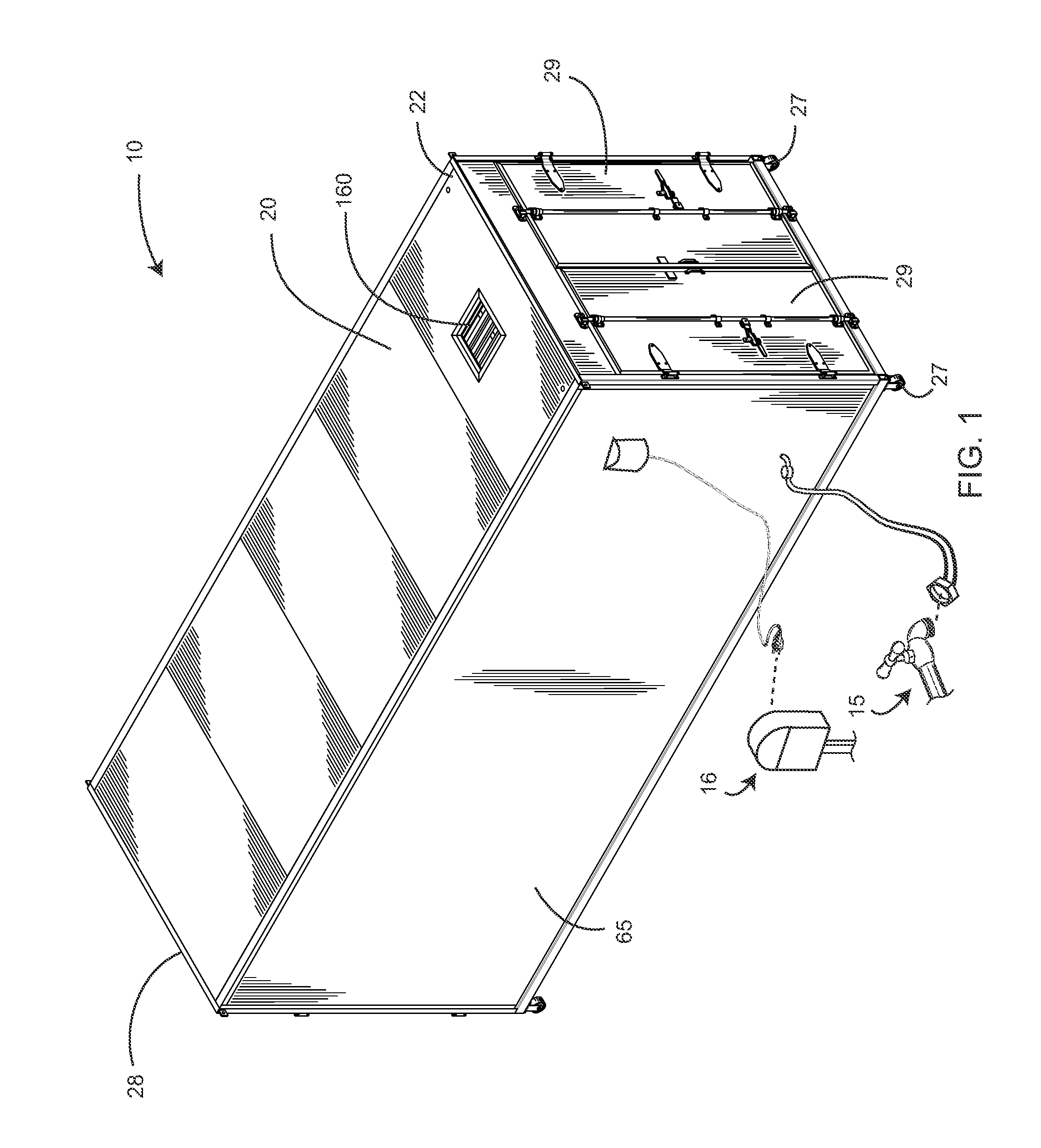
A transportable fodder production unit is disclosed that includes an insulated container having a front end and a rear end, a plurality of trays each having drain apertures through a bottom side thereof, a racking system for supporting each of the trays with a plurality of shelves extending from the front end of the container to the rear end of the container, an irrigation system attachable to a water source and having a water tank in fluid communication with a plurality of spray heads through a pump and a plurality of pipes, a lighting system that maintains a predetermined illumination within the container, a thermal control system that maintains the temperature inside the container within a predetermined temperature range, and a central control system for activating the other systems and maintaining electrical load balancing on a power source.

Description

CROSS-REFERENCE TO RELATED APPLICATIONS[0001]This application is a continuation-in-part of U.S. patent application Ser. No. 12 / 282,953, filed on Dec. 3, 2008, and incorporated herein by reference.STATEMENT REGARDING FEDERALLY SPONSORED RESEARCH AND DEVELOPMENT[0002]Not Applicable.FIELD OF THE INVENTION[0003]The present invention relates to the production of fodder. In particular, the present invention relates to a fodder production unit.DISCUSSION OF RELATED ART[0004]There have been many systems proposed for the intensive production of fodder in order to provide feed for livestock. Systems have been proposed that range from simple trays in which seeds are grown, through hydroponic systems to various automated systems. The main difficulty with all of these systems for producing fodder is achieving sufficient fodder production in an economical manner.[0005]Systems involving the production of fodder in trays is a batch-wise process that results in the harvesting of large quantities of ...

Claims


Application Information

Patent Timeline
IPC IPC(8): A01G31/00
CPCA01G31/06A01G9/16Y02A40/25Y02P60/21A01G31/02
Inventor COLLESS, TERRYRACCANELLO, FLAVIO
Owner COLLESS TERRY
Why Eureka
Try Eureka