Automated layer by layer spray technology

a technology of spraying technology and polymer, applied in the direction of coatings, membranes, transportation and packaging, etc., can solve the problems of affecting the degree of transfer from the rinse bath to the subsequent polyelectrolyte solution, the individual layer pair may take upwards of thirty minutes to deposit, and the choice of polyelectrolyte solvent is thereby typically limited. , to achieve the effect of being scalabl

Active Publication Date: 2012-08-07
MASSACHUSETTS INST OF TECH
View PDF19 Cites 107 Cited by
  • Summary
  • Abstract
  • Description
  • Claims
  • Application Information

AI Technical Summary

Benefits of technology

[0010]The problems of the prior art have been overcome by the present invention, which comprises an automated apparatus capable of spray depositing polyelectrolytes layer by layer (LbL) with minimal or no human interaction. In certain embodiments, the apparatus sprays atomized polyelectrolytes onto a vertically oriented substrate. To counteract the effects of irregular spray patterns, the substrate is preferably slowly rotated about a central axis. In certain embodiments, the apparatus also includes a forced pathway for the droplets, such as a pathway created by using a vacuum. In this way, a thicker or three-dimensional substrate can be coated. In certain embodiments, the modular apparatus is designed so as to be scalable. In other words, through the use of multiple instantiations of the apparatus, a large or irregularly shaped substrate can be coated. Rolls of textile can therefore be coated using the apparatus. Additionally, the present invention includes a method to uniformly coat a substrate, such as a hydrophobic textile material, using aqueous solutions of polyelectrolytes.

Problems solved by technology

While this procedure as described is able to produce extremely uniform films as thin as one nanometer per layer pair, it is not uncommon that an individual layer pair may require upwards of thirty minutes to deposit.
The choice of polyelectrolyte solvent is thereby typically limited to those solvents with relatively low vapor pressure, such as water, to avoid evaporation and species concentration during extended dipping periods.
In the case of an absorbent substrate, such as fabric, the cyclic nature of the dipping process can lead to a degree of carryover from the rinse baths to the subsequent polyelectrolyte solutions.
This carryover can induce an observable change in the pH of the polyelectrolyte solutions, which may be unacceptable in certain cases.
As stated above, the traditional Layer by Layer process is very time consuming.
Thus, there exists a diffusion time scale, which is inversely proportional to the diffusivity of the polyelectrolyte through the solvent, limiting the rate of deposition.
However, such a method cannot reduce the quality or uniformity of the layers that are deposited, since these factors are critical.

Method used


Image

  • Automated layer by layer spray technology
  • Automated layer by layer spray technology
  • Automated layer by layer spray technology

Examples


Embodiment Construction

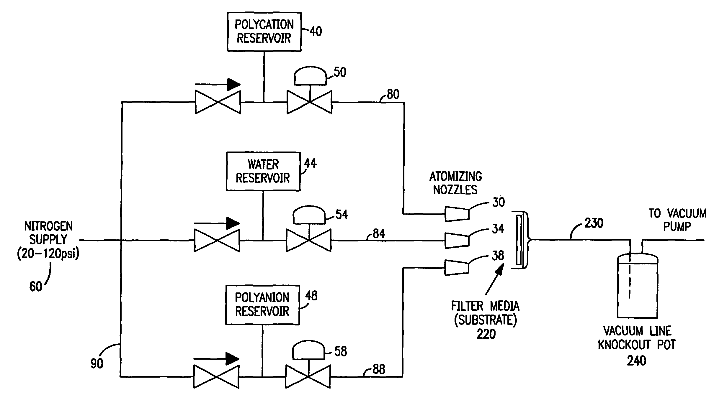
[0020]FIG. 1 represents one embodiment of the present invention. An automated spray system 10 is depicted which can be used to coat substrate 20 using a layer by layer methodology. In the preferred embodiment, at least three atomizing nozzles 30, 34, 38 are used to spray the substrate 20. Each of these nozzles is in communication with a corresponding reservoir 40, 44, 48. These reservoirs are used to hold the materials that are conventionally held in baths for traditional LbL dipping processes. Thus, polyelectrolytes of opposing charge are held in two of the reservoirs 40, 48, while the remaining reservoir is used to hold water or other suitable fluid for the rinse cycle. Those skilled in the art will appreciate that although reservoirs 40, 44 and 48 are shown, other embodiments can be used that provide each nozzle in communication with a suitable supply of appropriate fluid. Preferably, the rinse fluid used is deionized water (DI). The contents of these reservoirs are pressurized, ...


PUM

PropertyMeasurementUnit
pressureaaaaaaaaaa
pressureaaaaaaaaaa
timeaaaaaaaaaa

Abstract

The present invention comprises an automated apparatus capable of spray depositing polyelectrolytes via the LbL mechanism with minimal or no human interaction. In certain embodiments, the apparatus sprays atomized polyelectrolytes onto a vertically oriented substrate. To counteract the effects of irregular spray patterns, the substrate is preferably slowly rotated about a central axis. In certain embodiments, the apparatus also includes a forced pathway for the droplets, such as a pathway created by using a vacuum. In this way, a thicker or three-dimensional substrate can be coated. In certain embodiments, the apparatus is designed so as to be scalable. Thus, through the use of multiple instantiations of the apparatus, a large or irregularly shaped substrate can be coated. Rolls of textile can therefore be coated using the apparatus. Additionally, the present invention includes a method to uniformly coat a substrate, such as a hydrophobic textile material, using aqueous solutions of polyelectrolytes.

Description

[0001]This application claims priority of U.S. Provisional Application Ser. No. 60 / 843,360, filed Sep. 8, 2006, the disclosure of which is incorporated herein by reference.[0002]The U.S. Government has a paid-up license in this invention and the right in limited circumstances to require the patent owner to license others on reasonable terms as provided for by the terms of Grant No. DAAD19-02-D-0002, awarded by the Army Research Office.BACKGROUND OF THE INVENTION[0003]Over the past decade, the technique of polymer thin film deposition known as “Layer-by-Layer” has proven its versatility in creating very uniform films of precisely controllable thickness, even on the nanometer length scale. This process is commonly used to assemble films of oppositely charged polyelectrolytes electrostatically, but other functionalities such as hydrogen bonding can be the driving force for film assembly. Typically, this deposition process involves the submersion of a substrate having an inherent surfac...

Claims


Application Information

Patent Timeline
Patent Type & Authority Patents(United States)
IPC IPC(8): B05B3/00B05B7/06B05C13/02B05C11/00
CPCD06M15/61D06M15/233B01D67/0088D06M15/263B05D1/02D06M15/3562D06M23/06D06M15/3566B05D7/50D06M23/005Y10T428/25B01D2323/26B01D2323/02B05B1/14B05D3/00B05D7/04
Inventor KROGMAN, KEVIN C.HAMMOND, PAULA T.ZACHARIA, NICOLE S.
Owner MASSACHUSETTS INST OF TECH
Why Eureka
Try Eureka