Endoscope assembly with retroscope

a retroscope and endoscope technology, applied in the field of endoscopes, can solve the problems of increasing discomfort, complications, and risks for patients, and the camera of the endoscope, and achieve the effect of improving the field of view

Inactive Publication Date: 2012-08-07
PSIP LLC
View PDF350 Cites 75 Cited by
  • Summary
  • Abstract
  • Description
  • Claims
  • Application Information

AI Technical Summary

Benefits of technology

[0014]The steerable imaging device according to this aspect of the invention allows a physician to better locate the imaging device, resulting in a greater viewing field and allowing viewing of the areas behind folds and flexures. The steerable imaging device is advantageous also because it allows a greater degree of movement due to its smaller diameter and greater flexibility as compared to an imaging device mounted on the distal end of the insertion tube.
[0016]In a preferred embodiment, the distal end region of the insertion tube may include a circular groove having a front-facing sidewall and a rear-facing sidewall. The rear-facing sidewall has a window placed in front of the rear-viewing imaging device. Alternatively, the rear-viewing imaging device may protrude outside of the rear-facing sidewall so that a window is not needed. The groove of this embodiment provides the imaging device with a better field of view.
[0017]In another preferred embodiment, the distal end region of the insertion tube includes a circular protrusion having a front-facing side and a rear-facing side. The rear-facing side of the protrusion has a window placed in front of the rear-viewing imaging device. Alternatively, the rear-viewing imaging device protrudes outside of the rear-facing side of the protrusion so that a window is not needed. The circular protrusion of this embodiment provides the imaging device with a better field of view.

Problems solved by technology

Repositioning and movement of the endoscope prolongs the procedure and causes added discomfort, complications, and risks to the patient.
Additionally, in an environment such as the lower gastro-intestinal tract, flexures, tissue folds and unusual geometries of the organ may prevent the endoscope's camera from viewing all areas of the organ.
The unseen area may cause a potentially malignant (cancerous) polyp to be missed.

Method used


Image

  • Endoscope assembly with retroscope
  • Endoscope assembly with retroscope
  • Endoscope assembly with retroscope

Examples


Embodiment Construction

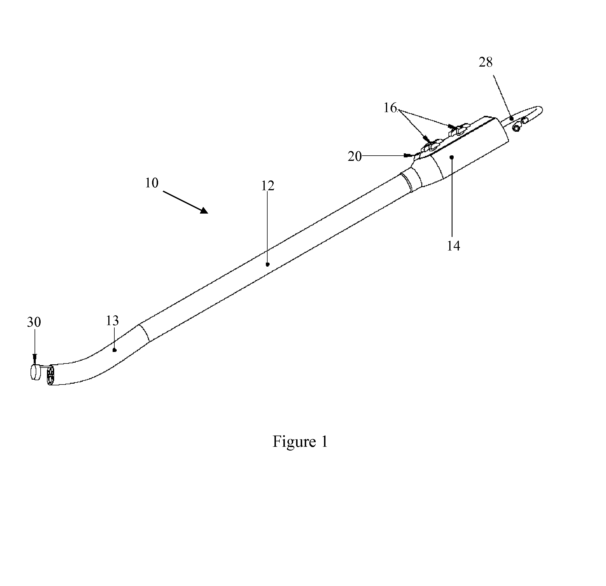
[0039]FIG. 1 illustrates a first exemplary endoscope 10 of the present invention. This endoscope 10 can be used in a variety of medical procedures in which imaging of a body tissue, organ, cavity or lumen is required. The types of procedures include, for example, anoscopy, arthroscopy, bronchoscopy, colonoscopy, cystoscopy, EGD, laparoscopy, and sigmoidoscopy.

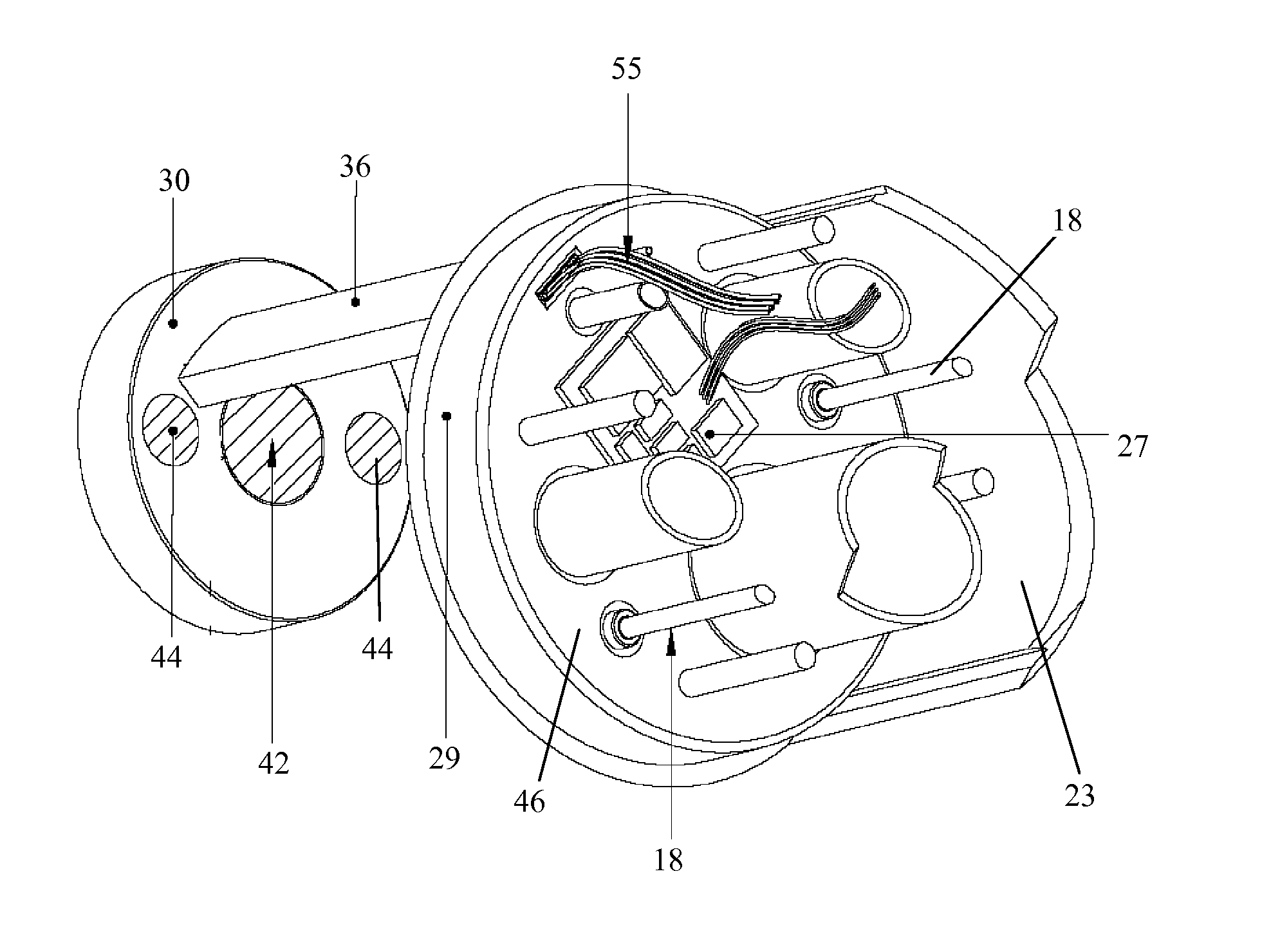
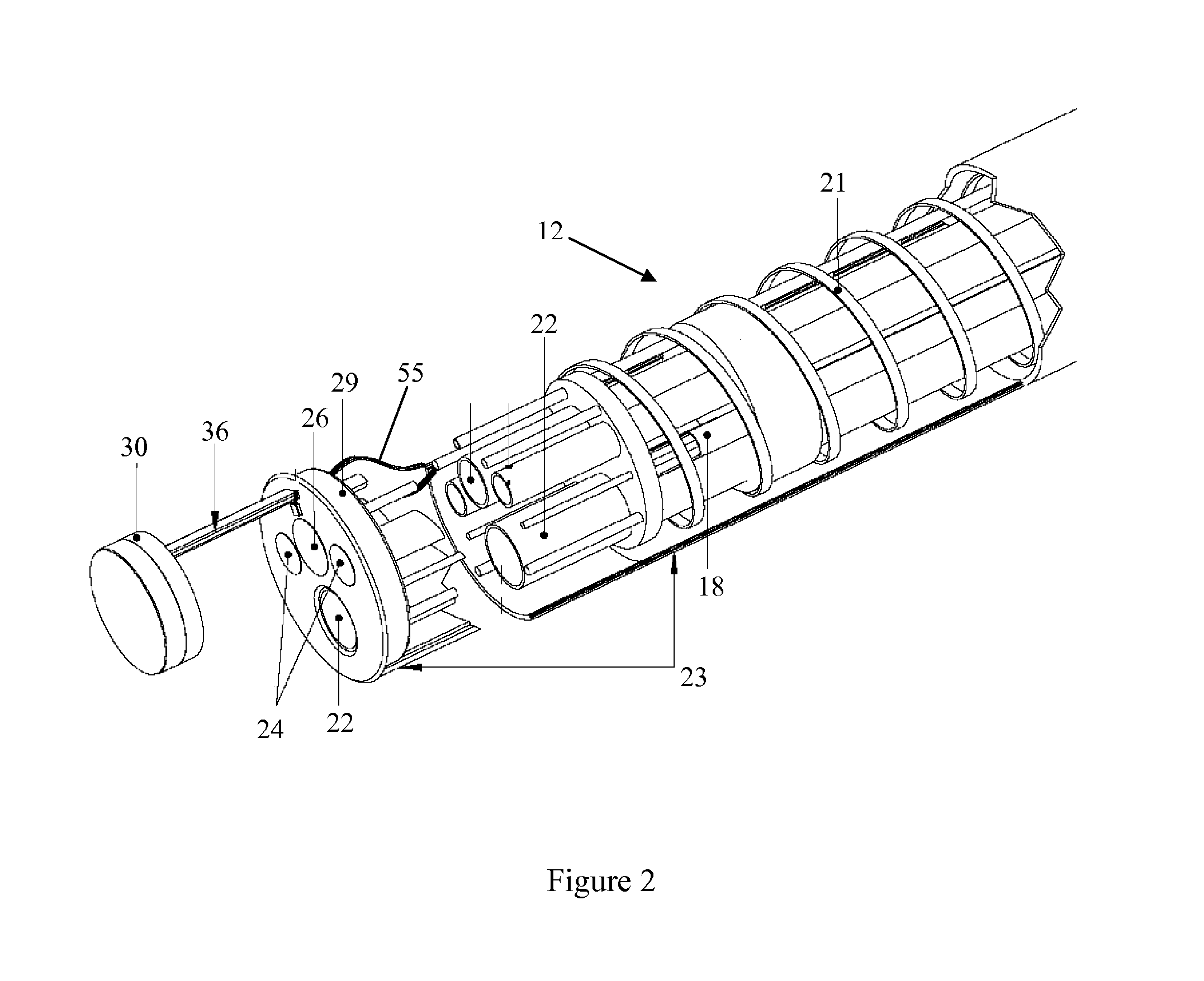
[0040]The endoscope 10 of FIG. 1 may include an insertion tube 12 having a main imaging device 26 at its distal end (FIG. 2), a control handle 14 connected to the insertion tube 12, and a secondary imaging device 30 positioned at the distal end of the endoscope 10.

[0041]The insertion tube 12 of the endoscope 10 may be detachable from the control handle 14 or may be integrally formed with the control handle 14. The diameter, length and flexibility of the insertion tube 12 depend on the procedure for which the endoscope 10 is used.

[0042]As shown in FIG. 2, the insertion tube 12 preferably has one or more longitudinal channels 22 ...


PUM


Abstract

An endoscope includes an insertion tube having a distal end and an imaging device with a steerable extension. The proximal end of the extension is attached to the distal end of the insertion tube. An endoscope includes an insertion tube having a distal end region and a rear-viewing imaging device at least partially disposed inside the distal end region. An endoscope includes an insertion tube having a distal end cap, an imaging device, and a link that couples the imaging device to the distal end cap of the insertion tube.

Description

[0001]This application claims the benefit of U.S. Provisional Patent Application No. 60 / 761,475, filed Jan. 23, 2006, the entire disclosure of which is incorporated herein by reference.[0002]This application additionally claims the benefit of U.S. Provisional Patent Application No. 60 / 802,056, filed May 19, 2006, the entire disclosure of which is incorporated herein by reference.[0003]This application further claims the benefit of U.S. patent application Ser. No. 11 / 609,838, filed Dec. 12, 2006, the entire disclosure of which is incorporated herein by reference.[0004]The entire disclosure of U.S. patent application Ser. No. 11 / 609,660, filed Aug. 29, 2005, is incorporated herein by reference.TECHNICAL FIELD OF THE INVENTION[0005]The present invention relates to an endoscope.BACKGROUND OF THE INVENTION[0006]An endoscope is a medical device comprising a flexible tube and a camera mounted on the distal end of the tube. The endoscope is insertable into an internal body cavity through a ...

Claims


Application Information

Patent Timeline
Patent Type & Authority Patents(United States)
IPC IPC(8): A61B1/06
CPCA61B1/00177A61B1/00181A61B1/005A61B1/0052A61B1/05A61B1/053A61B1/273A61B1/00174A61B1/00186A61B1/015A61B1/018A61B1/31A61B1/00193A61B1/0676A61B1/0623A61B1/051
Inventor BAYER, LEXRASMUSSEN, FRED
Owner PSIP LLC
Why Eureka
Try Eureka