Removable nozzle for use with air cannons and aerators and method for replacing same

a technology of air cannon and aerator, which is applied in the field of nozzles, can solve the problems of air cannon nozzles in such applications being worn, periodically replacing, and air cannon nozzles being subject to extreme environmental conditions

Active Publication Date: 2012-08-07
MARTIN ENG
View PDF14 Cites 4 Cited by
  • Summary
  • Abstract
  • Description
  • Claims
  • Application Information

AI Technical Summary

Benefits of technology

[0007]Accordingly, it is an object of the present invention to provide an air cannon nozzle which is easier and hence less costly to replace, once installed in association with an air cannon and a material handling vessel.
[0008]It is another object of the present invention of the present invention to provide an air cannon nozzle which is suitable for use in both ambient and high temperature environments.
[0009]It is yet another object of the present invention to provide an air cannon nozzle which is capable of withstanding high temperature environments for prolonged periods of time.

Problems solved by technology

Depending upon the material handling application, air cannon nozzles can be subject to extreme environmental conditions.
As a result, air cannon nozzles in such applications become worn over time, and must be periodically replaced.
With prior art air cannon nozzles, periodic replacement of the nozzles can be a significantly time consuming and costly undertaking, particularly when, as mentioned above, a single pre-heater tower at a cement plant may have in excess of one hundred nozzles in need of replacement, as may occur during a scheduled annual maintenance shutdown.

Method used


Image

  • Removable nozzle for use with air cannons and aerators and method for replacing same
  • Removable nozzle for use with air cannons and aerators and method for replacing same
  • Removable nozzle for use with air cannons and aerators and method for replacing same

Examples


Embodiment Construction

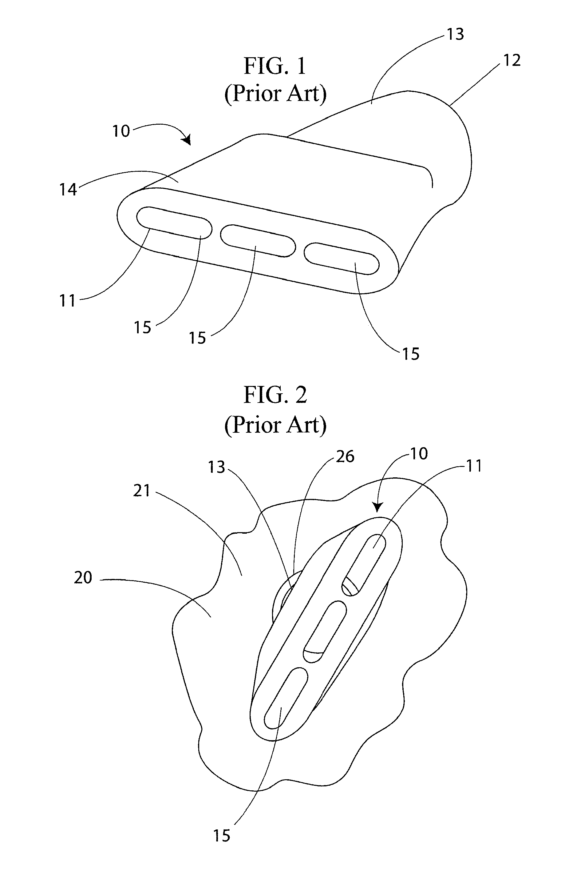
[0031]A prior art air cannon nozzle 10 is shown in FIG. 1 as comprising outlet port 11, inlet port 12, cylindrical inlet portion 13, and flattened, frusto-conical outlet portion 14. As shown in FIG. 1, outlet port 11 may include a plurality of openings 15, all in communication with an interior region of the nozzle. For high temperature environments, prior art air cannon nozzles are typically cast from a grade of steel suitable for sustained exposure to high temperatures, such as grade 310 stainless steel.

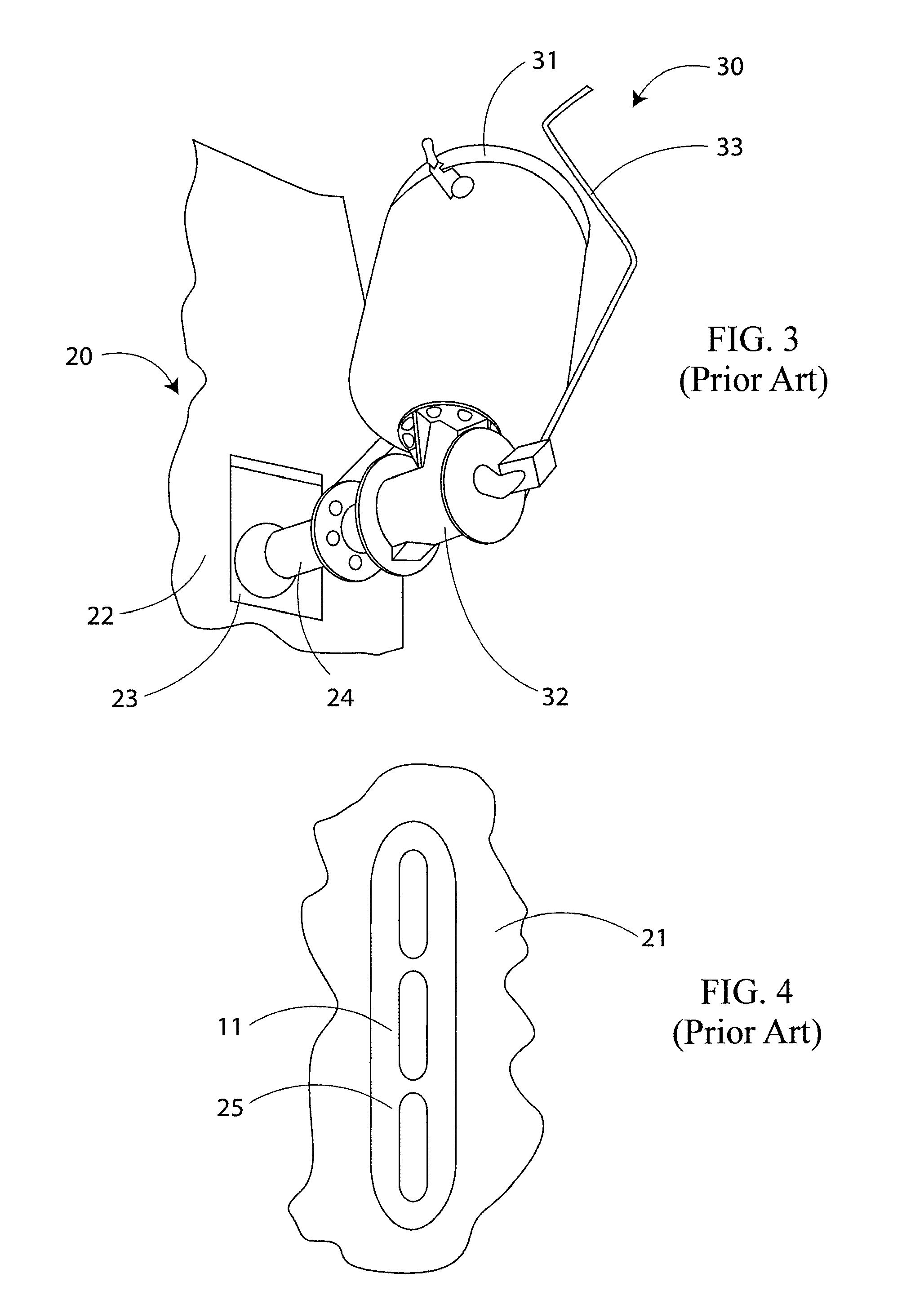
[0032]Prior art air cannon nozzle 10 is further shown within the interior region of an associated industrial vessel 20 in FIG. 2. Outlet port 11 is directed towards the interior of the vessel, and cylindrical inlet portion 13 of the prior art air cannon nozzle extends beyond inner surface 21 of the vessel, through aperture 26 to the exterior of the vessel, where it may be welded to an extension pipe for fluid communication with an exhaust valve of an air cannon.

[0033]Such prior art ...


PUM

PropertyMeasurementUnit
temperaturesaaaaaaaaaa
thicknessaaaaaaaaaa
temperaturesaaaaaaaaaa

Abstract

A nozzle for introducing pressurized fluids into an industrial vessel is releasably attachable to and detachable from a mounting member securedly attached to an exterior surface of the vessel. The mounting member is attached, via extension piping, to a source of pressurized gas, such as the exhaust valve of an air cannon. Both the nozzle and the mounting member include respective mating collars which engage each other in a twist lock manner. Additional securing members are provided to securely retain the nozzle and mounting member in twist lock engagement. Removal of the nozzle is performed by releasing the securing members, twisting the nozzle from inside of the vessel to unlock it from the mounting member, and uncoupling the nozzle from the mounting member. Installation of a replacement nozzle is performed by performing the foregoing steps in the reverse order. For high temperature applications, the removal of existing refractory material may be necessary prior to removal of a worn nozzle, and new refractory material may be applied to the interior surface of the vessel following attachment of the replacement nozzle.

Description

CROSS-REFERENCE AND PRIORITY CLAIM TO RELATED PATENT APPLICATION[0001]This patent application claims priority to provisional patent application Ser. No. 60 / 914,328, entitled “Removable Nozzle for Use With Cannons and Aerators and Method for Replacing Same”, filed Apr. 27, 2007, the entire disclosure of which is incorporated herein by reference.FIELD OF THE INVENTION[0002]The present invention relates, in general, to the removal of flowable materials that has coagulated or caked in an area of a material handling system, and, more specifically, to nozzles for introducing pressurized fluids, such as gasses discharged by air cannons or aerators, into the interior of a vessel of a material handling system.BACKGROUND OF THE INVENTION[0003]Air cannons and other aeration equipment are often employed in association with material handling vessels in order to supply a discharge of compressed air to the vessel, so as to dislodge buildups and enhance the flow of material within the vessels. An a...

Claims


Application Information

Patent Timeline
Patent Type & Authority Patents(United States)
IPC IPC(8): C21B7/16
CPCB65D88/703C21B7/163F27D3/16C21C5/5217C21C5/462Y10T137/86372Y02P10/20
Inventor MILLER, TRAVIS J.PRONSCHINSKE, BRADLEY E.MASTERSON, MICHAEL J.YEPSEN, MARTIN A.
Owner MARTIN ENG
Why Eureka
Try Eureka