
Car navigation system

a technology for navigation systems and cars, applied in the field of car navigation systems, can solve the problems of increasing and increasing seriousness, affecting the user's experience, and requiring efficient use of vehicle energy, and achieve the effect of reducing energy consumption

Active Publication Date: 2012-08-07
CLARION CO LTD
View PDF6 Cites 22 Cited by
  • Summary
  • Abstract
  • Description
  • Claims
  • Application Information

AI Technical Summary

Benefits of technology

The invention is a car navigation system that predicts how much fuel a vehicle will use on a specific route based on information from a previous test cycle and the vehicle's specifications. The system calculates the energy consumption of the vehicle engine or motor based on the test cycle characteristic value and the vehicle's specifications, and predicts how much fuel will be used for each road link based on the vehicle's energy consumption parameters and the landform and traffic information for that link. This allows the system to search for a route that minimizes energy consumption. The invention is designed to make it easy for users to understand and reduce energy consumption while driving.

Problems solved by technology

With the environmental problem becoming more and more serious, the efficient use of energy for vehicles is required.
It is difficult for the user, however, to set the parameters for the engine or the motor which requires the special knowledge, and the user has no choice but to set the vehicle parameters based on the information generally available from the catalog of the vehicle involved or the information acquired from the sensors mounted on the vehicle.
The emission test cycle fuel consumption rate, however, represents the value of energy consumption for the distance covered according to a prescribed emission test cycle procedure, and therefore, a highly accurate prediction value reflecting the landform and the traffics along the running route cannot be obtained from the value of the emission test cycle fuel consumption rate.
Thus, the problem is posed that it is difficult to search for a route minimizing the energy consumption accurately.

Method used


Image

  • Car navigation system
  • Car navigation system
  • Car navigation system

Examples


first embodiment

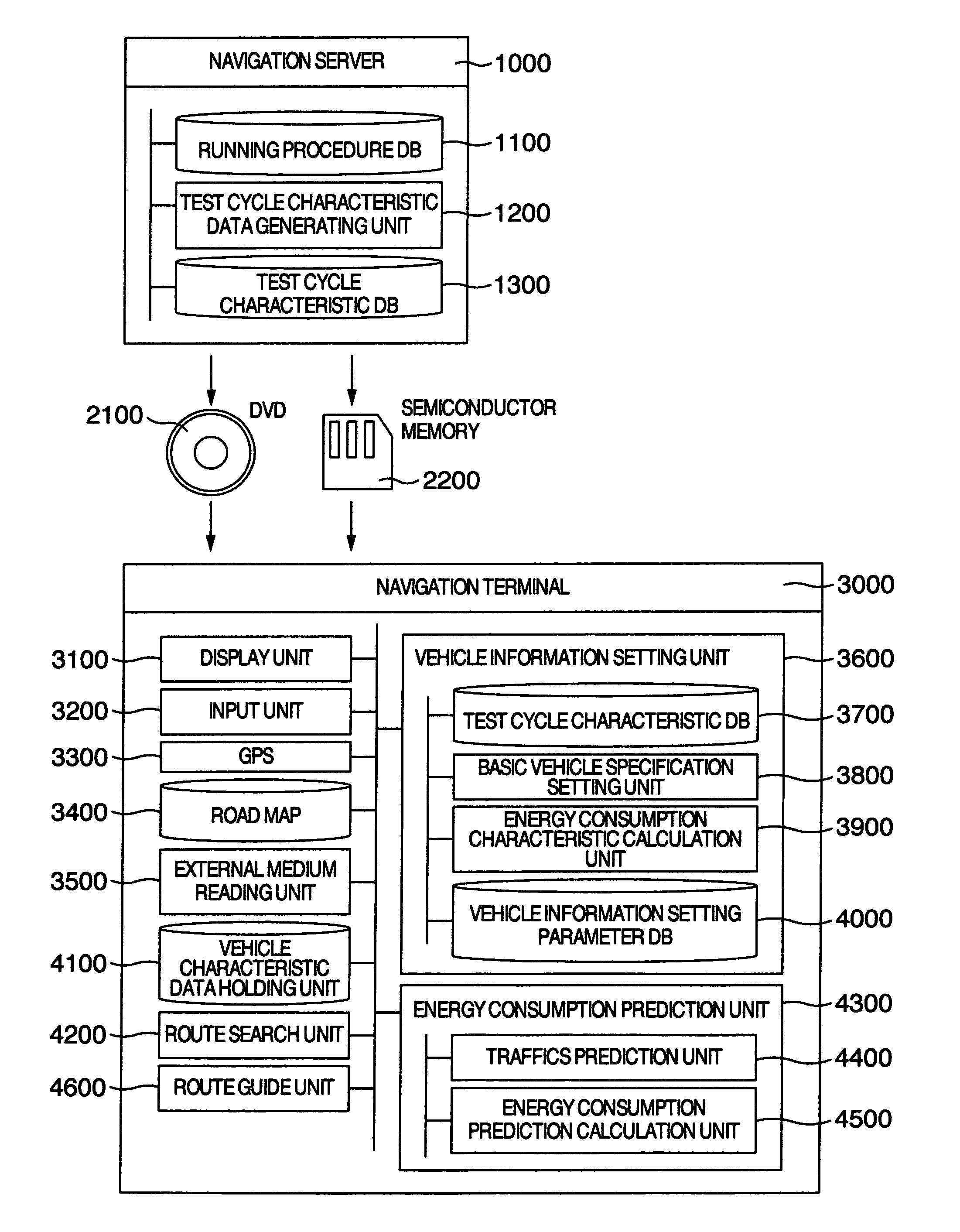
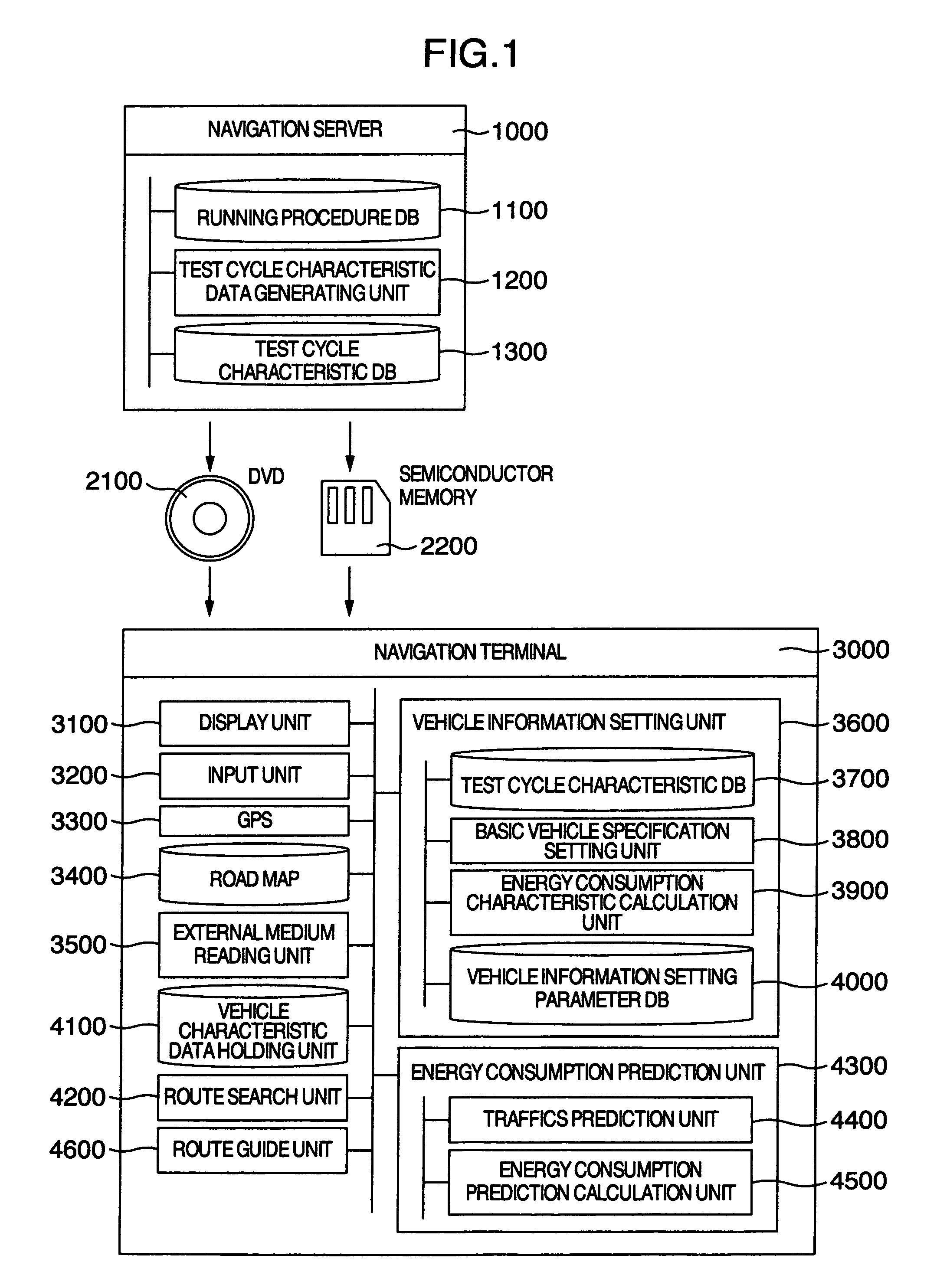
[0041]FIG. 1 is a diagram showing the configuration of a car navigation system according to the present invention. The car navigation system shown in FIG. 1 includes a navigation server 1000 and a navigation terminal 3000.

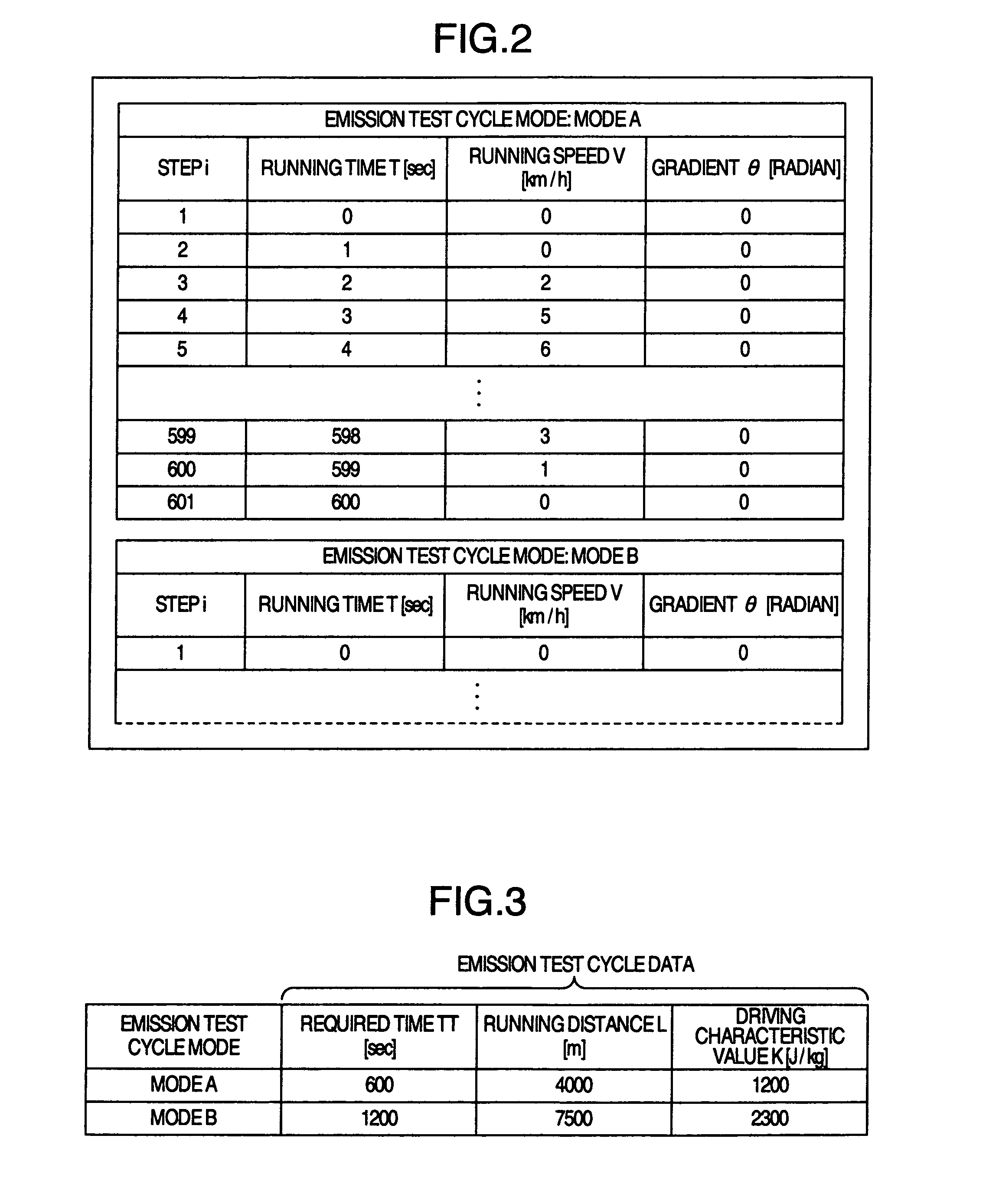
[0042]The navigation server 1000 includes a running procedure DB 1100, a test cycle characteristic value generating unit 1200 and a running characteristic DB 1300. The running procedure DB 1100 stores the running procedure for measuring the emission test cycle fuel consumption rate. FIG. 2 shows an example of the format of the running procedure stored in the running procedure DB 1100. As shown in FIG. 2, the running procedure is stored as the information on the relation, in each emission test cycle mode defined for each running step, between the running time, the running speed and the gradient of the running section. In the running step i of the emission test cycle involved as described below, the running time is designated as T(i), the running speed as V(i) and th...

second embodiment

[0093]Next, a modification of the first embodiment is explained as a second embodiment. The car navigation system according to the second embodiment is different from the system according to the first embodiment only in the vehicle information setting unit of the navigation terminal 3000. FIG. 16 shows the configuration of the vehicle information setting unit 36000 according to the second embodiment.

[0094]The vehicle information setting unit 36000 according to the second embodiment has substantially the same configuration as the vehicle information setting unit 36000 according to the first embodiment, and includes a test cycle characteristic DB 3700, a basic vehicle specification setting unit 38000, an energy consumption characteristic calculation unit 39000 and a vehicle information setting parameter DB 40000.

[0095]As compared with the vehicle information setting parameter DB 4000 according to the first embodiment, the vehicle information setting parameter DB 40000 stores therein o...

third embodiment

[0106]Now, another modification of the first embodiment is explained as a third embodiment. The car navigation system according to the third embodiment is different from the car navigation system according to the first embodiment only in the vehicle information setting unit of the navigation terminal 3000. FIG. 19 shows the configuration of the vehicle information setting unit 36500 according to the third embodiment. The vehicle information setting unit 36500 according to the third embodiment includes a test cycle characteristic DB 3700, a basic vehicle specification setting unit 38500, an energy consumption characteristic calculation unit 39500, an energy consumption sensor 40500, a vehicle speed sensor 41500 and a vehicle information setting parameter DB 42500.

[0107]The energy consumption sensor 40500 is for measuring the energy consumption of the vehicle, and provided by a measurement means such as a wattmeter in the case where the motive power supply type is the electric vehicle...


PUM


Abstract

A car navigation system solves the problem that the emission test cycle fuel consumption rate indicates the energy consumption per unit distance covered following a prescribed emission test cycle procedure, and therefore, cannot produce a highly accurate prediction value reflecting the landform and the traffics along a route. So, the test cycle characteristic values independent of the vehicle model for vehicle energy consumption in a specified running condition are calculated, and the vehicle energy consumption parameter of the engine or the motor is estimated from the basic vehicle specifications such as the vehicle weight, the power supply type, the emission test cycle fuel consumption rate, the test cycle characteristic values in the emission test cycle and the vehicle characteristics. Using the basic vehicle specifications and the energy consumption parameter, the energy consumption is predicted taking the landform and traffics into consideration.

Description

INCORPORATION BY REFERENCE[0001]The present application claims priority from Japanese application JP 2009-204237 filed on Sep. 4, 2009, the content of which is hereby incorporated by reference into this application.BACKGROUND OF THE INVENTION[0002]This invention relates to a car navigation system for predicting the energy consumption of an automotive vehicle.[0003]With the environmental problem becoming more and more serious, the efficient use of energy for vehicles is required. In view of this, demand has increased for an application of a car navigation system which can search for a route minimizing the energy consumption. Such an application requires a technique for predicting the amount of energy consumed along the route searched for. Incidentally, the energy consumption described herein includes the consumption of electric energy for an electric vehicle, the fuel consumption for a gasoline engine vehicle or a diesel engine vehicle and the amount of energy consumed by each motive...

Claims


Application Information

Patent Timeline
Patent Type & Authority Patents(United States)
IPC IPC(8): G06F19/00
CPCG01C21/3469
Inventor KONO, TOSHIAKIFUSHIKI, TAKUMI
Owner CLARION CO LTD
Learn More