Electric lawn mower having a sub frame supporting transaxles and motor drivers

a technology of motor drivers and electric lawn mowers, which is applied in the direction of vehicle position/course/altitude control, process and machine control, instruments, etc., can solve the problems of increasing costs and labor, complicated wiring between electric components, and reducing the efficiency of transmitting electric power to electric motors, so as to efficiently cool the motor drivers

Active Publication Date: 2012-08-14
YANMAR CO LTD +1
View PDF21 Cites 31 Cited by
  • Summary
  • Abstract
  • Description
  • Claims
  • Application Information

AI Technical Summary

Benefits of technology

[0008]The electric lawn mower further comprises a controller supported by the sub frame to control the motor drivers. Therefore, mounting the controller onto the electric lawn mower can be easily completed only by connecting the sub frame supporting the controller to the main frame, and a wiring between the controller and the motor drivers can be shortened to enhance efficiency of transmitting electric power to the electric motors and to reduce costs and labor.
[0017]Alternatively, the motor and the motor driver are provided with respective oil-resisting cable connection guides for guiding connection of the cable to the motor and the motor driver freely from the oil in the transaxle housing. Therefore, even if the cable is extended in the transaxle housing so as to be exposed to the oil in the transaxle housing, the oil-resisting cable connection guides surely protect an electrical connection portion of the motor to the cable and an electrical connection portion of the motor driver to the cable from the oil.

Problems solved by technology

However, these electric components for driving the drive wheels are severally mounted onto a vehicle body frame of the lawn mower so as to increase labor and processes for manufacturing the lawn mowers.
Further, wiring among the electric components may be complicated or elongated so as to reduce efficiency of transmitting electric power to the electric motors and to increase costs and labor.

Method used


Image

  • Electric lawn mower having a sub frame supporting transaxles and motor drivers
  • Electric lawn mower having a sub frame supporting transaxles and motor drivers
  • Electric lawn mower having a sub frame supporting transaxles and motor drivers

Examples


Embodiment Construction

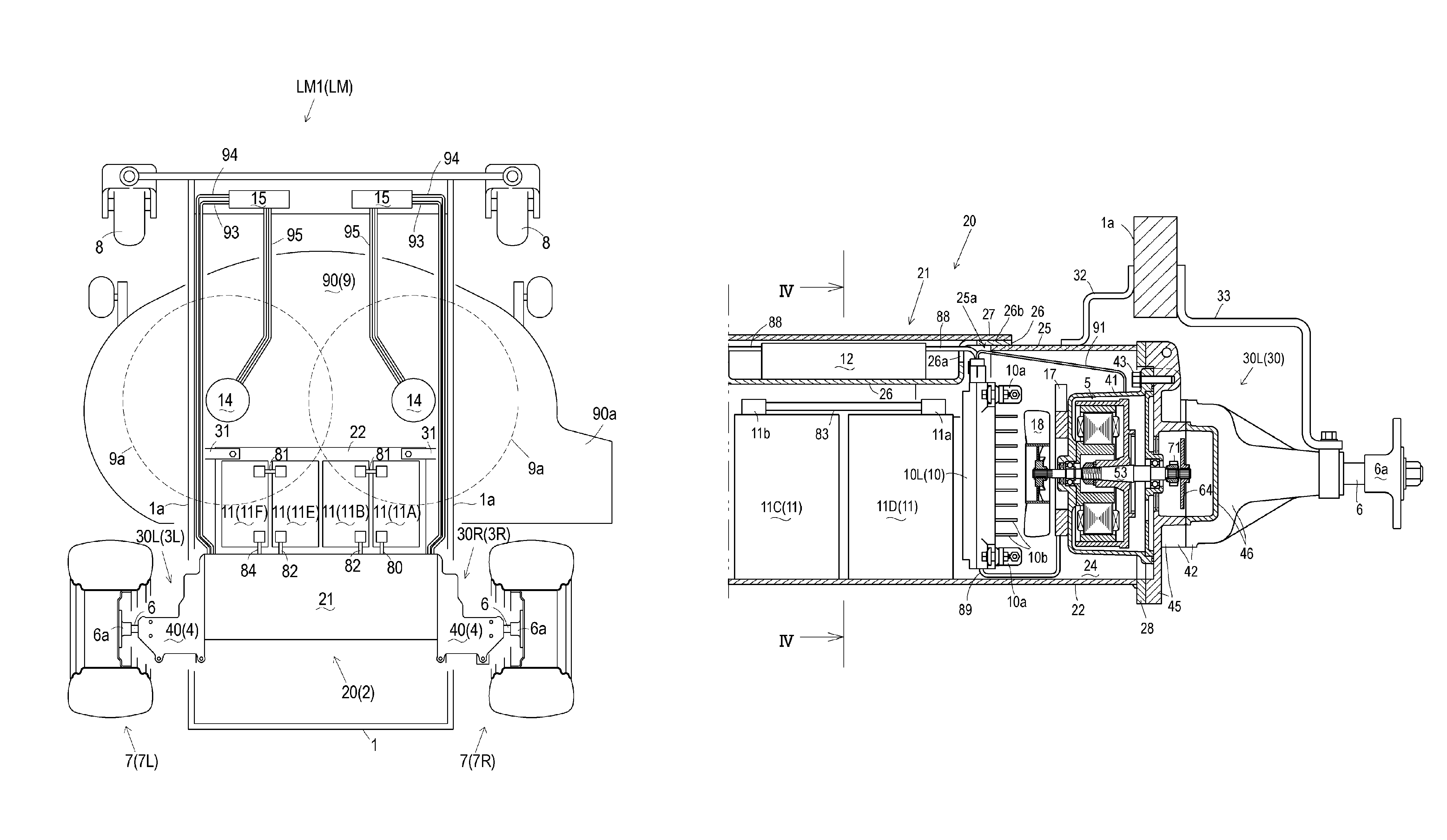
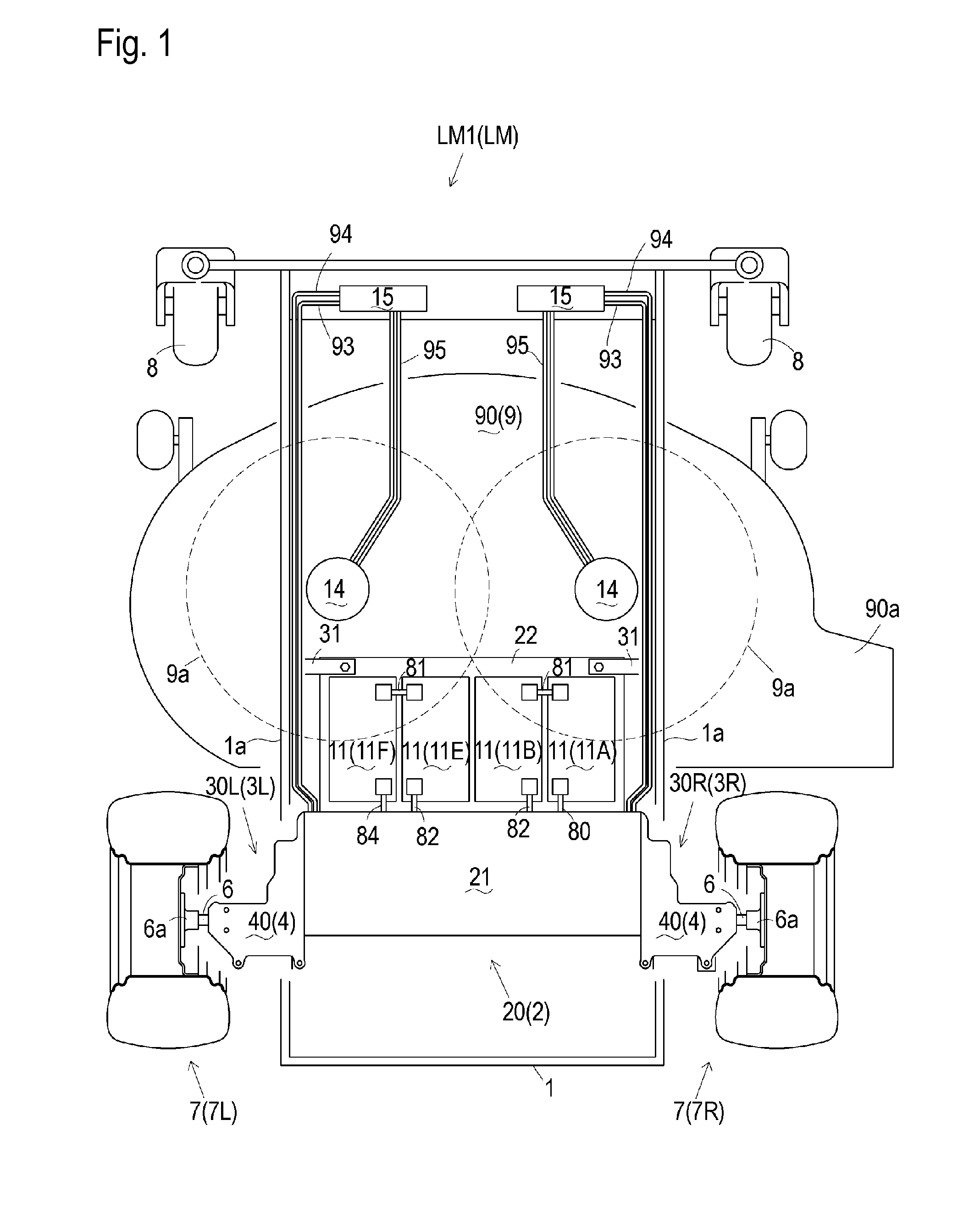
[0033]An electric lawn mower LM is referred to as a generic name for each of electric lawn mowers LM1, LM2 and LM3 disclosed in this application. A general structure of a lawn mower LM will be described with reference to FIGS. 1, 6, 10 and other drawings for describing a common structure shared among lawn mowers LM1, LM2 and LM3.

[0034]Lawn mower LM includes a main frame 1 having right and left side portions 1a which are extended in the fore-and-aft direction of lawn mower LM. Main frame 1 supports a mower deck 9 incorporating at least one rotary mowing blade 9 and supports at least one castor 8. Incidentally, dotted circles marked by reference numerals 9a in each of FIGS. 1, 6 and 10 designate rotation loci of mowing blades 9a.

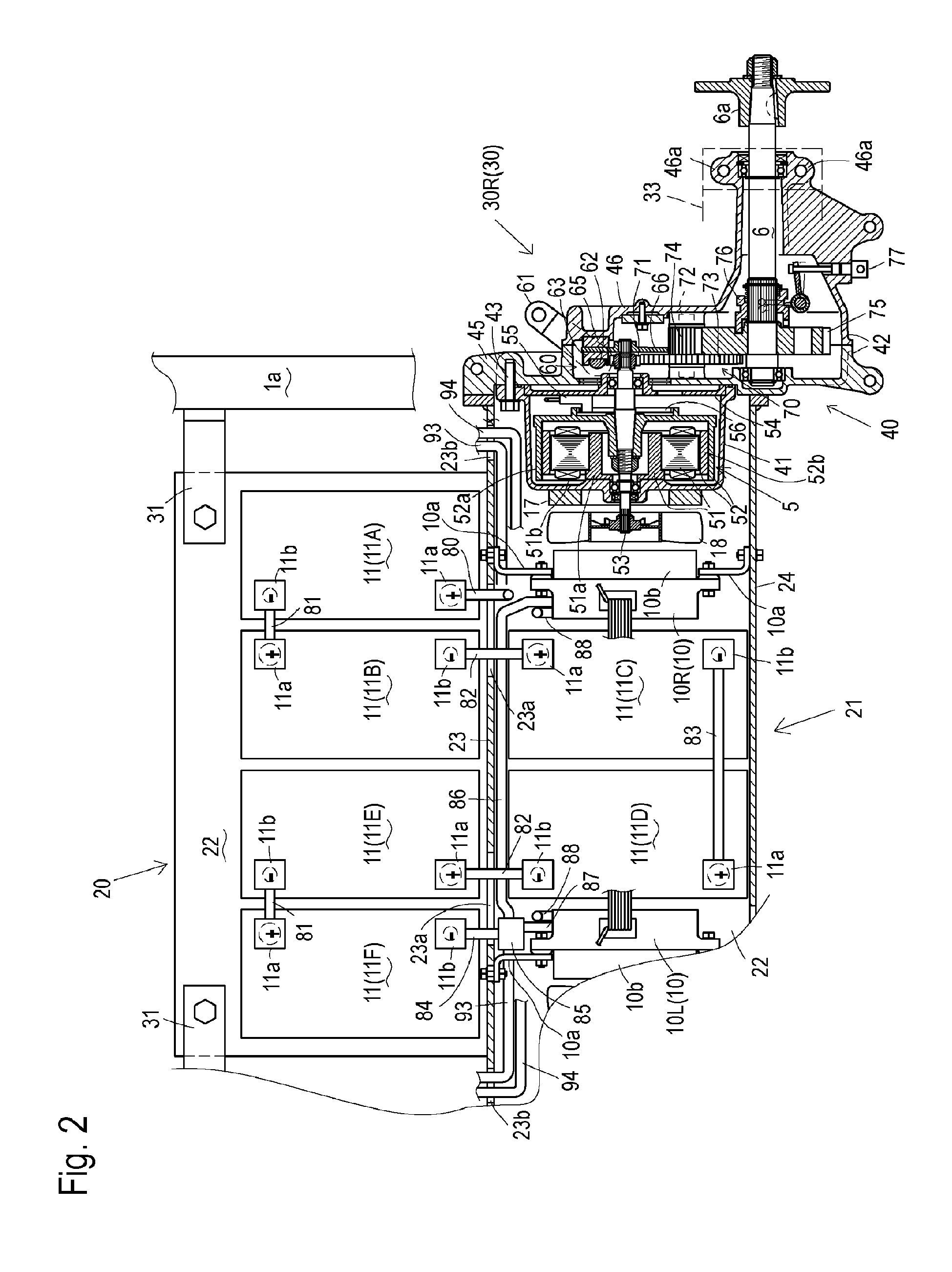
[0035]Main frame 1 is assembled with a sub frame 2 so as to constitute a vehicle body of lawn mower LM. Sub frame 2 supports right and left transaxles 3R and 3L (generically named as “transaxles 3”) at right and left end portions thereof. Each of transaxles 3...


PUM


Abstract

An electric lawn mower includes a main frame, a mower deck supported by the main frame, a castor supported by the main frame, a sub frame, a pair of transaxles, and a pair of motor drivers. Each of the transaxles includes a transaxle housing, an electric motor disposed in the transaxle housing, a single axle supported by the transaxle housing, and a drive wheel fixed on the axle outside of the transaxle housing. The motor drivers supply electric power to the respective motors of the respective transaxles. The sub frame, supporting the transaxles and the motor drivers, is connected to the main frame.

Description

CROSS REFERENCE TO RELATED APPLICATION[0001]This application claims the benefit of U.S. Provisional Application No. 61 / 348,921, filed May 27, 2010, which is hereby incorporated by reference in its entirety.BACKGROUND OF THE INVENTION[0002]1. Field of the Invention[0003]The present invention relates to an electric lawn mower equipped with a pair of right and left transaxles, each of which supports a single axle and incorporates an electric motor for driving the axle.[0004]2. Related Art[0005]There are conventional electric lawn mowers equipped with a pair of right and left transaxles carrying respective right and left drive wheels. The right and left transaxles are provided with respective electric motors for driving the respective drive wheels. To drive and control the electric motors of the right and left transaxles, each of the conventional electric lawn mowers is further equipped with a controller, a battery, and motor drivers, which occupy a large part of weight of the electric ...

Claims


Application Information

Patent Timeline
Patent Type & Authority Patents(United States)
IPC IPC(8): B60K1/00B60K16/00B60L8/00
CPCA01D34/78A01D69/02Y02T10/90Y02T10/7072
Inventor SASAHARA, KENGOEBIHARA, TOMOYUKINAKAGAKI, MITSUHIROMORIGUCHI, KAZUMAMATSUMOTO, KEIJI
Owner YANMAR CO LTD
Why Eureka
Try Eureka