Turbine inter-stage gap cooling and sealing arrangement

a technology of inter-stage gap cooling and sealing arrangement, which is applied in the direction of machines/engines, liquid fuel engines, mechanical equipment, etc., can solve the problems of inability to remove the statator vanes of the aero engine from the engine, the over-temperature issue is more pronounced, and the adjacent vane assembly cannot be removed from the engin

Inactive Publication Date: 2012-08-14
FLORIDA TURBINE TECH
View PDF18 Cites 39 Cited by
  • Summary
  • Abstract
  • Description
  • Claims
  • Application Information

AI Technical Summary

Benefits of technology

[0010]It is therefore an object of the present invention to provide for an industrial gas turbine engine which limits the injection of hot gas in the gap formed between the isolation ring and the adjacent stator vane assembly.

Problems solved by technology

An aero engine does not use these isolation rings because of the heavy weight.
As such, the stator vanes in the aero engine cannot be removed from the engine without disassembling the entire turbine section.
As a result, hot gas flows in and out along the inter-stage gaps and an over-temperature occurs at the blade outer air seal edges and the blade isolation ring corresponding to the hot gas injection location. this over-temperature issue is more pronounced when a lack of adequate inter-stage gap purge air for the axial gap exists in combination with a strong bow wave induced by the low solidity vane airfoil creates a high circumferential pressure variation that will force the hot gas into the inter-stage gap.
Thus, the adjacent vane assembly cannot be removed from the engine without disassembling the shroud segments as well.
Also, the Riedmiller patent lacks the use of the isolation rings to support the shroud segments.

Method used


Image

  • Turbine inter-stage gap cooling and sealing arrangement
  • Turbine inter-stage gap cooling and sealing arrangement
  • Turbine inter-stage gap cooling and sealing arrangement

Examples


Embodiment Construction

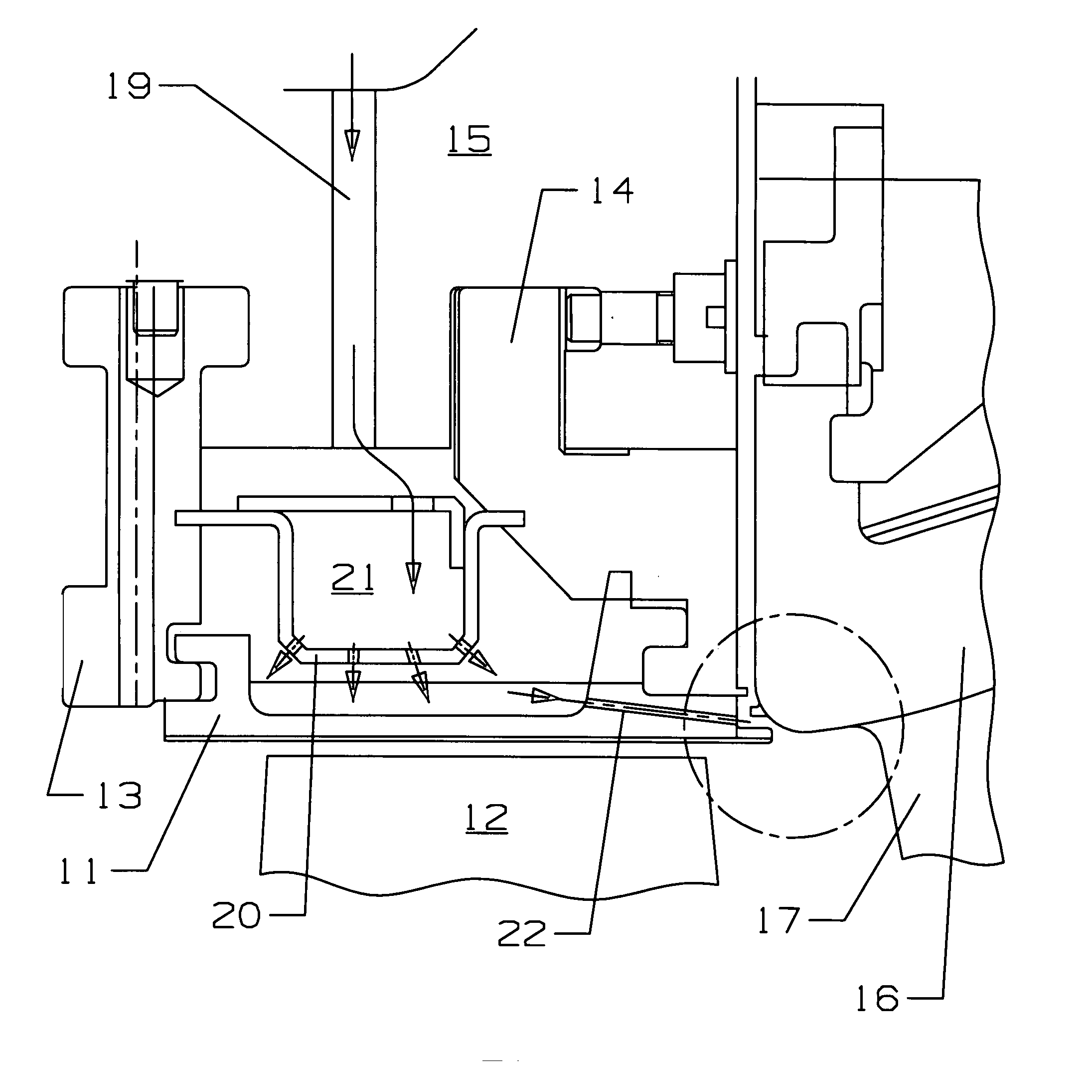
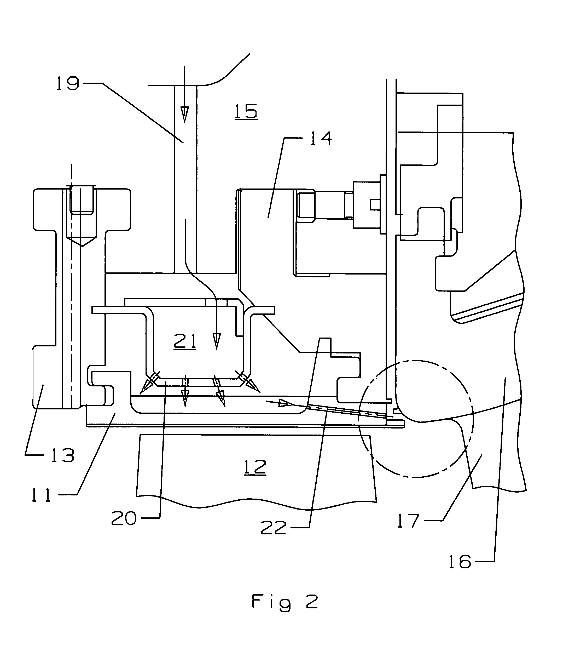
[0017]The present invention is a cooling and sealing apparatus and method for an outer diameter inter-stage gap between the first blade ring and the second ring of an industrial gas turbine engine. FIG. 2 shows the first stage turbine rotor blade and outer shroud segment structure adjacent top the second stage stator vane assembly. The turbine rotor blade 12 includes a blade tip that forms a gap between the outer shroud segment 11. The outer shroud segment 11 is secured within a forward isolation ring 13 and an aft isolation ring 14, both isolation rings being secured to the turbine casing 15. An impingement plate 20 with impingement holes forms a cavity 21 in which cooling air is supplied through a cooling hole 19 in the turbine casing 15. A stator vane outer endwall 16 with a vane airfoil 17 extending from the endwall is secured to the turbine casing 15 adjacent to the aft isolation ring 14 and blade shroud segment 11 and forms an inter-stage axial gap between in which the hot gas...


PUM


Abstract

An industrial gas turbine engine having a first stage rotor blade with a outer segmented shroud forming a blade outer air seal with the blade tips and a second stage stator vane assembly which forms an axial inter-stage gap between an isolation ring that supports the outer shroud segment and the outer endwall of the vane. The isolation ring and the outer endwall both include a circumferential rail extending into the gap to form a serpentine flow passage in the gap. The outer shroud segment includes an aft edge extending outward to form the serpentine flow passage within the gap. Cooling air holes in the aft edge of the outer shroud segment discharge cooling air from the impingement cavity located above the shroud segment into a continuous slot opening into the inner end of the serpentine flow passage in the gap.

Description

FEDERAL RESEARCH STATEMENT[0001]None.CROSS-REFERENCE TO RELATED APPLICATIONS[0002]None.BACKGROUND OF THE INVENTION[0003]1. Field of the Invention[0004]The present invention relates generally to an industrial gas turbine engine, and more specifically to a cooling and sealing arrangement for a first stage blade outer air seal and second vane airfoil.[0005]2. Description of the Related Art including information disclosed under 37 CFR 1.97 and 1.98[0006]In a gas turbine engine, a compressor delivers compressed air into a combustor to be burned with a fuel and produce a hot gas flow, which is then passed through a turbine to drive the compressor and, in an industrial gas turbine (IGT) engine, also to drive an electric generator.[0007]An industrial gas turbine engine has several major design differences from an aero engine which is used to power an aircraft. An IGT is much larger and is designed to operate for long periods of time between shut-downs, typically in the range of 48,000 hours...

Claims


Application Information

Patent Timeline
Patent Type & Authority Patents(United States)
IPC IPC(8): F01D5/08
CPCF01D11/08F05D2240/11F05D2260/201Y02T50/676Y02T50/60
Inventor LIANG, GEORGE
Owner FLORIDA TURBINE TECH
Why Eureka
Try Eureka