Flow cell

a flow cell and flow tube technology, applied in the direction of positive displacement liquid engine, material analysis, liquid fuel engine components, etc., can solve the problems of difficult fabrication of this structure, waste of sample solution, limitation of decreasing the amount of sample solution, etc., to achieve measurement more reliably, increase pump capacity, and measure more reliably

Active Publication Date: 2012-08-14
NIPPON TELEGRAPH & TELEPHONE CORP
View PDF14 Cites 0 Cited by
  • Summary
  • Abstract
  • Description
  • Claims
  • Application Information

AI Technical Summary

Benefits of technology

[0012]According to the present invention, a fluidic channel is formed at almost the center of a plate-like member, so a liquid flowing through the fluidic channel can be measured more reliably. Since a pump is formed around the fluidic channel, the pump capacity can be increased to supply a large amount of liquid for a long time. As a result, the liquid can be measured more reliably.

Problems solved by technology

It is not easy to fabricate this structure.
A sample solution is wasted on the transfer path including the tube, which exerts a limitation on decreasing the amount of sample solution.
However, these paper chromatography methods have limitations in the shape of the fluidic channel and the like, and cannot perform complicated chemical analysis.

Method used


Image

  • Flow cell
  • Flow cell
  • Flow cell

Examples


first embodiment

[0028][First Embodiment]

[0029]The first embodiment according to the present invention will be described in detail with reference to the accompanying drawings.

[0030]

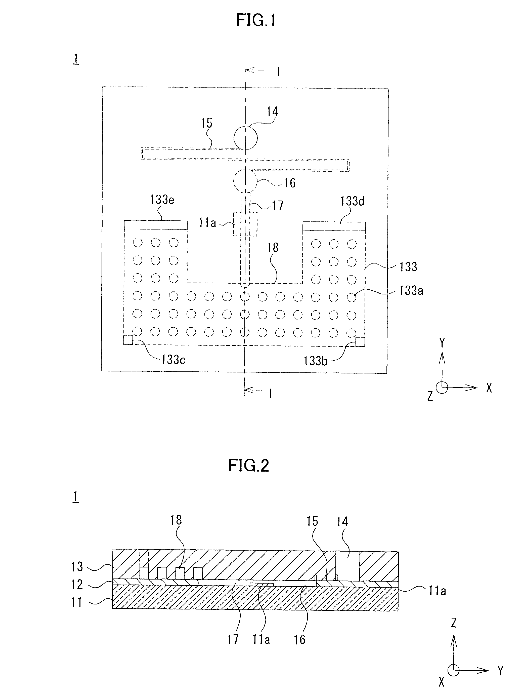
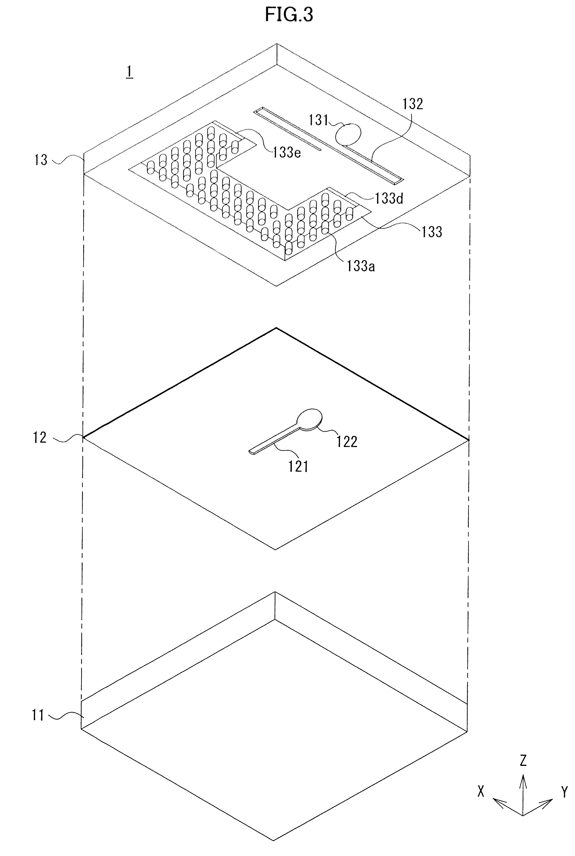
[0031]As shown in FIGS. 1 to 3, a flow cell 1 according to the first embodiment is formed from a first substrate 11 which has an almost rectangular shape when viewed from the top, a sheet-like member 12 which is disposed on the first substrate 11, and a second substrate 13 which is disposed on the sheet-like member 12. The first substrate 11, sheet-like member 12, and second substrate 13 are stacked to form one plate-like member. The flow cell 1 having this structure includes an inlet port 14 which passes through the second substrate 13 and allows introducing a sample solution, a suction pump 18 which is formed between the sheet-like member 12 and the second substrate 13, and a fluidic channel which connects the suction pump 18 and the inlet port 14. The fluidic channel is made up of a resistance fluidic channel 15 which ...

second embodiment

[0057][Second Embodiment]

[0058]The second embodiment according to the present invention will be described. In the second embodiment, suction pumps are arranged on the two sides of a measurement fluidic channel. In the second embodiment, the same reference numerals as those in the first embodiment denote the same parts, and a description thereof will be properly omitted.

[0059]

[0060]As shown in FIGS. 4 to 7, a flow cell 2 according to the second embodiment is formed from a first substrate 21 which has an almost rectangular shape when viewed from the top, a sheet-like member 22 which is disposed on the first substrate 21, and a second substrate 23 which is disposed on the sheet-like member 22. The flow cell 2 configured by stacking the substrates and sheet-like member includes an inlet port 24 which passes through the second substrate 23 and allows introducing a sample solution, two suction pumps 27 which are formed between the sheet-like member 22 and the second substrate 23, and a fl...

third embodiment

[0083][Third Embodiment]

[0084]The third embodiment according to the present invention will be described. The third embodiment is different from the second embodiment in the internal structure of the suction pump. In the third embodiment, the same reference numerals as those in the first and second embodiments denote the same parts, and a description thereof will be properly omitted.

[0085]

[0086]As shown in FIGS. 8 and 9, a flow cell 3 according to the third embodiment is formed from a first substrate 31 which has an almost rectangular shape when viewed from the top, a sheet-like member 32 which is disposed on the first substrate 31, and a second substrate 33 which is disposed on the sheet-like member 32. The flow cell 3 configured by stacking the substrates and sheet-like member includes an inlet port 34 which passes through the second substrate 33 and allows introducing a sample solution, two suction pumps 37 which are formed between the sheet-like member 32 and the second substrate...


PUM

PropertyMeasurementUnit
thicknessaaaaaaaaaa
thicknessaaaaaaaaaa
thicknessaaaaaaaaaa

Abstract

A measurement fluidic channel (17) is formed at almost the center of a flow cell (1). In general, the measurement region of a measurement apparatus is set to focus on almost the center of a measurement chip. When the flow cell (1) is mounted in the measurement apparatus, the focus of the measurement region is positioned just above the measurement fluidic channel (17). The measurement apparatus can more reliably measure a sample solution flowing through the measurement fluidic channel (17). A suction pump (18) is formed in regions around the measurement fluidic channel (17). When the flow cell has the same planar shape as a conventional one, the amount of sample solution which can be supplied can be increased, compared to a conventional structure in which components are formed in line. The time during which a sample solution flows through the fluidic channel can be prolonged, the amount of sample solution can be increased, and the measurement time can also be prolonged. A sample solution flowing through the fluidic channel can be measured more reliably.

Description

[0001]This is a non-provisional application claiming the benefit of international application number PCT / JP2009 / 051588 filed Jan. 30, 2009.TECHNICAL FIELD[0002]The present invention relates to a flow cell having a predetermined fluidic channel used for measurement by a measurement apparatus, and a pump for supplying a sample solution to the fluidic channel.BACKGROUND ART[0003]Measurement using a sophisticated biomolecule identification function such as an antigen-antibody reaction and binding of a DNA fragment (DNA probe) to DNA is becoming an important technique in clinical testing, measurement in the field of biochemistry, and measurement for environmental pollutants. Examples of the measurement are micro-TAS (Total Analysis Systems), micro combinatorial chemistry, chemical IC, chemical sensor, biosensor, microanalysis, electrochemical analysis, QCM measurement, SPR measurement, and ATR measurement. In the field of measurement, the amount of sample solution to be measured is often...

Claims


Application Information

Patent Timeline
Patent Type & Authority Patents(United States)
IPC IPC(8): G01N21/05G01N21/11
CPCF04B19/006G01N21/05B01L3/50273B01L3/502707Y10T436/2575B01L2300/069B01L2300/0816B01L2300/0887B01L2400/0406B01L2400/086G01N21/553G01N2021/056G01N2021/0346Y10T137/85978Y10T137/2224
Inventor MIURA, TORUHORIUCHI, TSUTOMUIWASAKI, YUZURUSEYAMA, MICHIKO
Owner NIPPON TELEGRAPH & TELEPHONE CORP
Why Eureka
Try Eureka