Radial compression mechanism with optimum die-to-die gap

Active Publication Date: 2012-08-21
WARRINER JEREMIAH J +2
View PDF3 Cites 20 Cited by
  • Summary
  • Abstract
  • Description
  • Claims
  • Application Information

AI Technical Summary

Benefits of technology

[0012]Another object of the invention is to provide a new and improved radial compression mechanism utilizing radially movable die that produce a large usable size range.
[0013

Problems solved by technology

A shortcoming of this type of mechanism is that there exists a gap between adjacent wedges, the size of which varies with the diameter of the cavity in an undesirable way.
The strict design tradeoffs for this type of mechanism results in a mechanism that must be large to provide a small maximum gap for a given diameter range, or a mechanism that must have a large gap to provide the same diameter range in a small size.
Large gaps between the wedges are a disadvantage because they allow space for parts of the compressed device to go into.
For example, the metal struts of a stent can move into the gap and be damaged.
A shortcoming of this mechanism is that it typically does not provide a sufficiently accurate positional relationship of the wedge-shape

Method used


Image

  • Radial compression mechanism with optimum die-to-die gap
  • Radial compression mechanism with optimum die-to-die gap
  • Radial compression mechanism with optimum die-to-die gap

Examples


Embodiment Construction

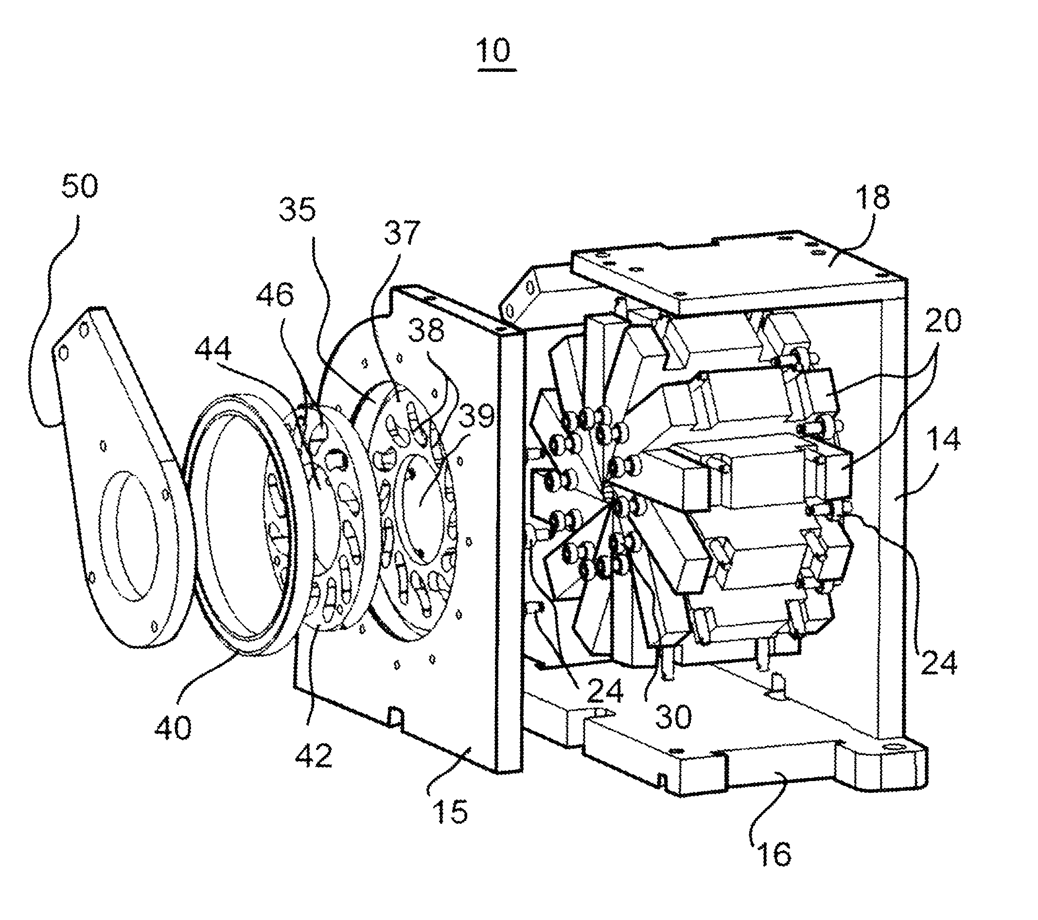
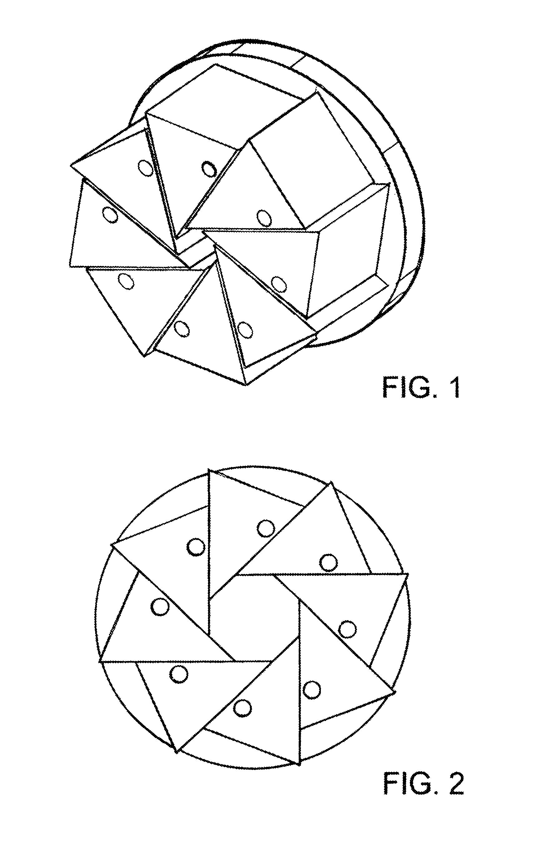
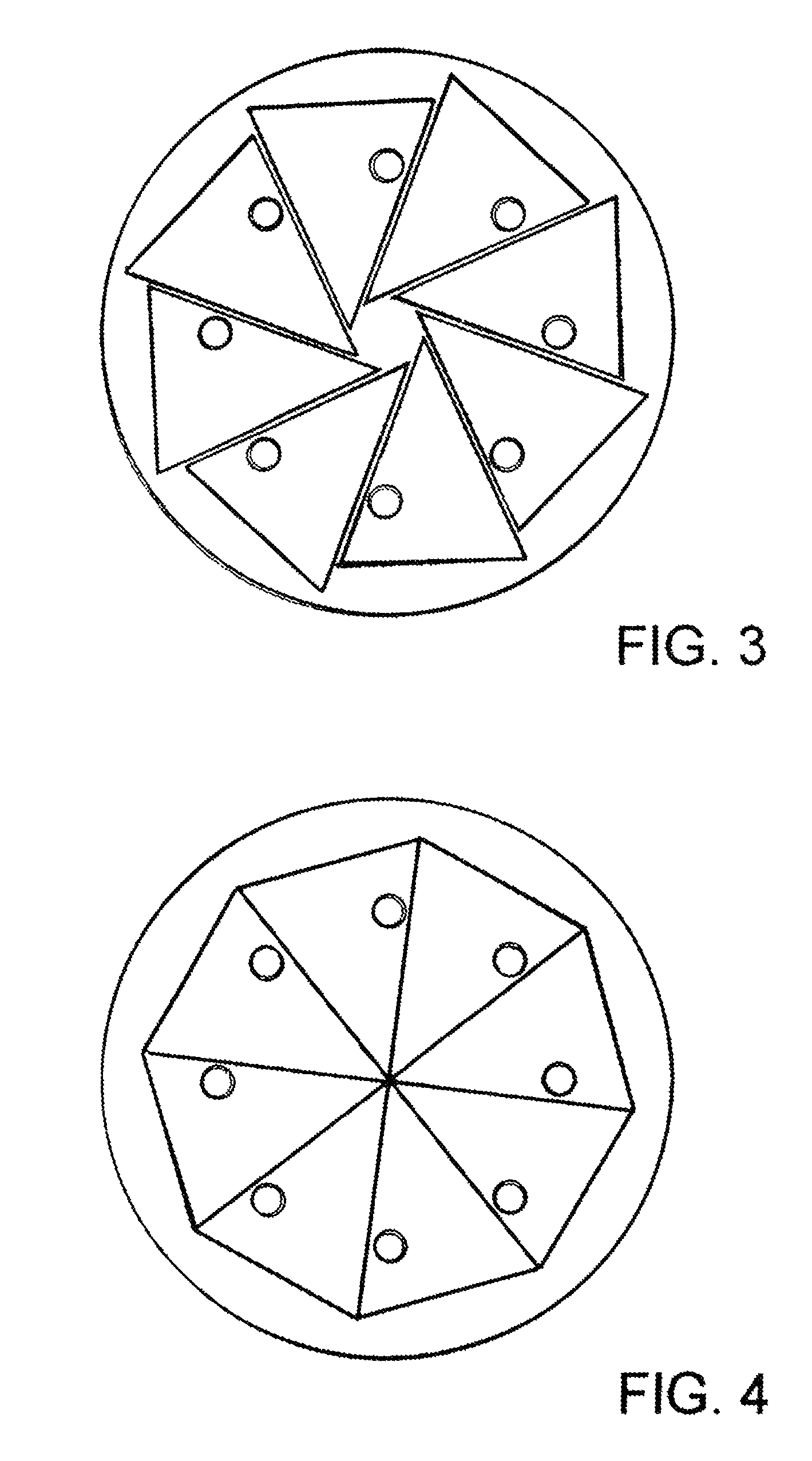
[0024]Turning now to the drawings, attention is first directed to FIGS. 10-13, which illustrate various side and internal views of a radial compression mechanism 10 in accordance with the present invention. Mechanism 10 includes a support or base, hereinafter referred to as a housing, 12 with a pair of spaced apart side members 14 and 15 affixed in position by a base 16 and upper cross plates 18. A plurality of generally wedge shaped dies 20 are arranged within housing 12 to form an approximately cylindrical (in this embodiment) central cavity 22 for receiving product to be compressed. In this description it will be understood that the term “product” generally means some medical item such as medical stents, balloons, catheters and the like, but could include other items. Dies 20 are positioned between side members 14 and 15 within housing 12 for generally radial movements by rollers or bearings 24 extending inwardly from each side member 14 and 15 into housing 12 and between adjacen...


PUM

PropertyMeasurementUnit
Diameteraaaaaaaaaa

Abstract

Radial compression mechanism includes a housing defining an inner chamber and a central opening for insertion and removal of product. A plurality of elongated compression dies are movably mounted for reciprocal movement within the inner chamber and define a central product receiving cavity coaxial with the axis of the central opening. Cam followers are affixed to the dies. First cam surfaces are affixed relative to the housing and second cam surfaces are movably mounted relative to the housing. Each cam follower engages a first cam surface to define a first position control constraint, and a second cam surface to define a second position control constraint. Each die has a position relative to each adjacent die and the coaxial central cavity that is controlled by the first position control constraint and the second position control constraint.

Description

CROSS REFERENCE TO RELATED APPLICATION[0001]This application claims the benefit of U.S. Provisional Patent Application No. 60 / 911,162, filed 11 Apr. 2007.FIELD OF THE INVENTION[0002]This invention generally relates to radial compression mechanisms and more specifically to mechanisms for compressing devices such as stents, catheters, balloons, and the like.BACKGROUND OF THE INVENTION[0003]In the manufacture and testing of medical devices, mechanisms are used to radially compress cylindrical devices such as stents, balloons, and catheters. For example, installation of a stent onto a catheter balloon is typically done by compressing the stent radially inward onto the balloon with enough pressure to permanently deform the stent to a smaller diameter and to slightly embed the metal stent into the plastic balloon. In another example, a polymer catheter balloon is compressed radially after pleating to wrap it tightly around the catheter shaft. In another example, a self-expanding stent is ...

Claims


Application Information

Patent Timeline
IPC IPC(8): B21D41/00B21D19/00B21J7/16B21J9/18
CPCB21J9/06Y10T29/49927
Inventor WARRINER, JEREMIAH J.GOFF, EDKNIGHT, JUSTIN
Owner WARRINER JEREMIAH J
Why Eureka
Try Eureka