Method for perforating failure-prone formations

a technology of perforation and formation, applied in the direction of fluid removal, borehole/well accessories, weapons, etc., can solve the problems of increasing the risk of formation failure, more reliable and less risky, and increasing so as to enhance the installation and longevity of a sand control completion. , the effect of reducing the propensity for sand production

Active Publication Date: 2012-08-21
WELLS FARGO BANK NAT ASSOC +1
View PDF18 Cites 3 Cited by
  • Summary
  • Abstract
  • Description
  • Claims
  • Application Information

AI Technical Summary

Benefits of technology

[0011]The present application provides an improved method for the perforation of failure-prone formations by using reactive shaped charges to reduce the propensity for sand production while increasing productivity in a sand co-production application. In one embodiment, the present invention uses reactive shaped charges to enhance the installation and longevity of a sand control completion. In another embodiment, the present invention provides for perforation without the subsequent installation of a sand control filter.
[0012]Conventional wisdom dictates that the additional release of energy in a sanding-prone formation is undesirable, as it could increase the risk of failure of the formation. However, it has been found that the controlled expulsion of debris from the perforation tunnels, which is provided by reactive shaped charges, is more reliable and less risky than conventional clean-up techniques such as surging or chemical treatments.
[0013]Using the method of the present invention, customary subsequent activity such as surge flow or post-perforation stimulation treatment is no longer necessary. Commercial flow rates of oil or gas can be extracted from the wellbore while applying a lower than normal pressure drawdown of a magnitude that would not induce formation failure or cause the onset of sand production. A second, local reaction within each cavity or perforated tunnel, expelling small amounts of material from a well actually produces a number of benefits. It enables the more efficient gravel packing of a well wherein a mechanical filter (i.e., “sand screen”) has been installed and ensures a substantially uniform distribution of inflow across a large number of entry points, resulting in a reduced risk of sand filter failure due to erosion and a reduced risk of voids forming where there is insufficient outflow of carrier fluid into the perforated interval. Second, in certain formations where the increased flow area resulting from perforation with reactive charges is sufficient to reduce the influx per open perforation to the point where excessive sand production is avoided, the present invention allows for perforation without subsequent installation of a sand control filter. Third, by using the present invention, increased longevity of mechanical sand control completions (sand screens) is achieved due to a reduced influx per perforation impinging on the sand screen as a result of increased number of open perforations and, where applicable, ideal packing of each perforation tunnel. Fourth, an improved outflow distribution is produced across the perforated interval during an extension pack or frac-and-pack completion due to higher percentage of producing cavities or disturbed regions of material. This results in an improved inflow potential and inflow distribution across the completed interval. Fifth, an improved production from wells where sand is co-produced with the hydrocarbons—typically heavy- and extra-heavy crude—is experienced with the present invention due to a greater number of enlarged, substantially debris-free tunnels and the onset of sand co-production being triggered by the reactive event in each tunnel.

Problems solved by technology

Conventional wisdom dictates that the additional release of energy in a sanding-prone formation is undesirable, as it could increase the risk of failure of the formation.
However, it has been found that the controlled expulsion of debris from the perforation tunnels, which is provided by reactive shaped charges, is more reliable and less risky than conventional clean-up techniques such as surging or chemical treatments.

Method used


Image

  • Method for perforating failure-prone formations
  • Method for perforating failure-prone formations
  • Method for perforating failure-prone formations

Examples


Embodiment Construction

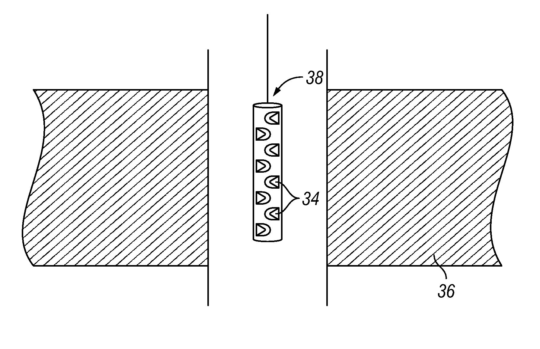
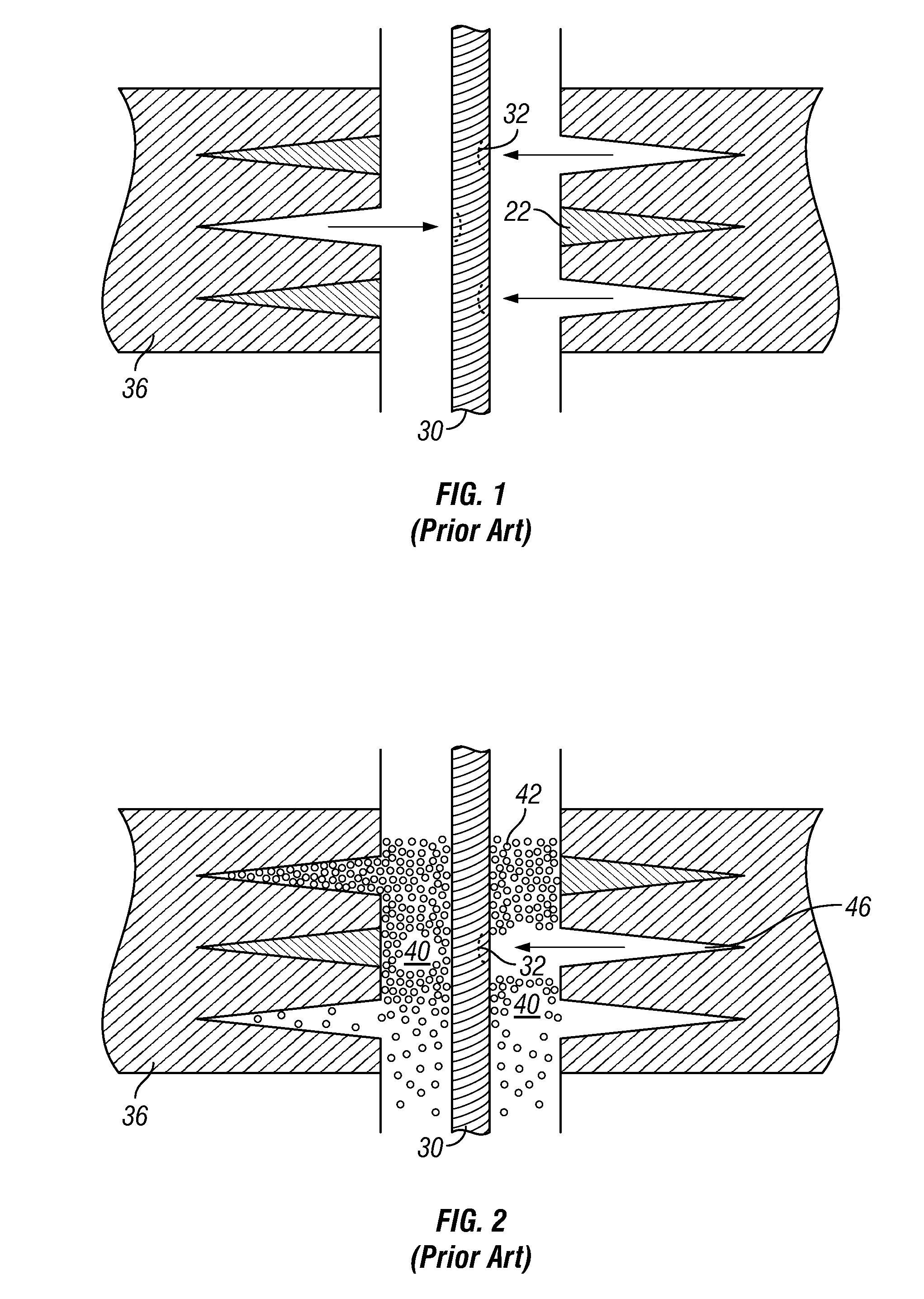
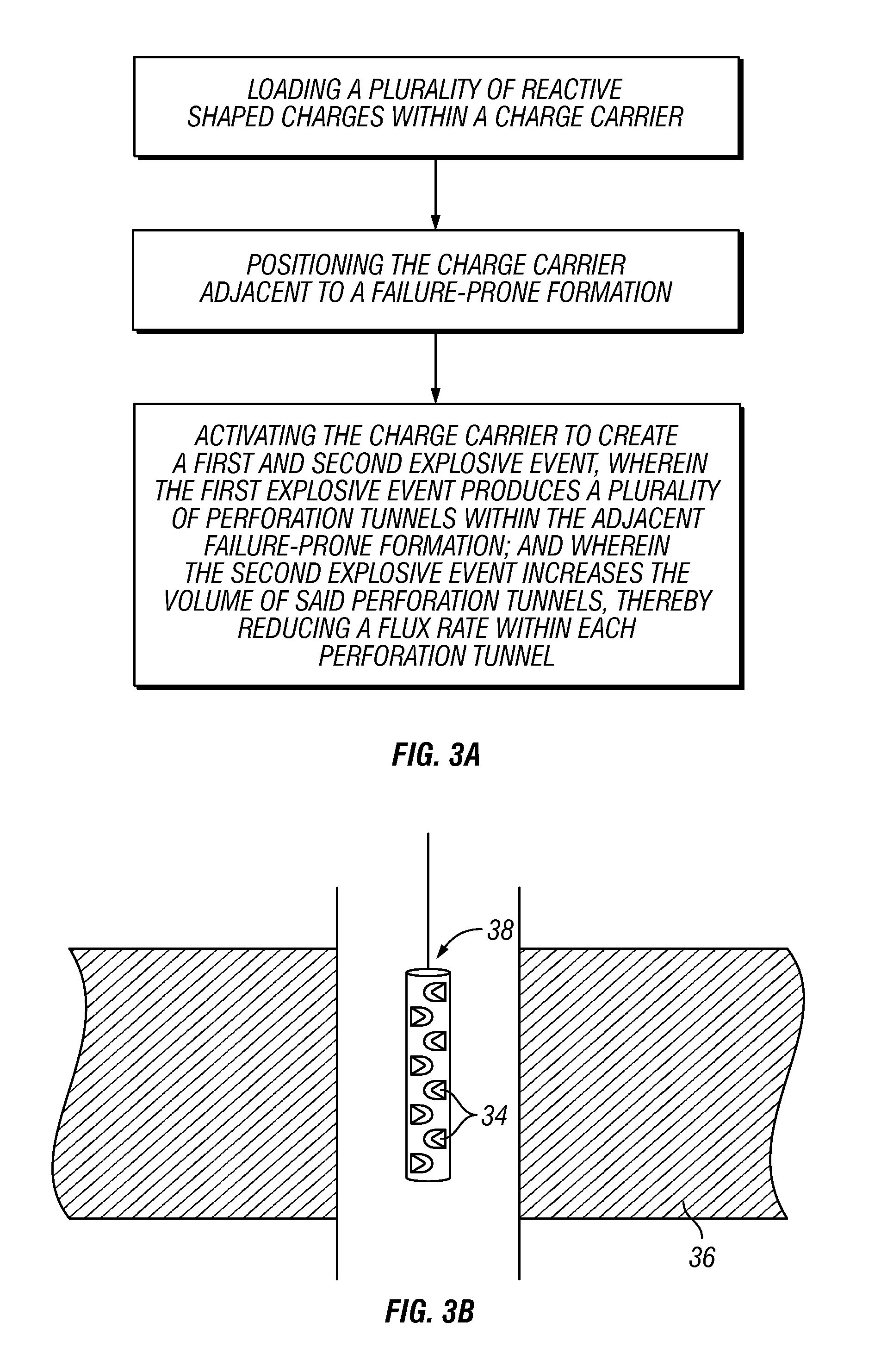
[0021]Current knowledge dictates that due to the poorly consolidated nature of failure prone formations, any additional energy or reactive detonation within a perforation tunnel would cause immediate production of formation and solids material into the wellbore. Therefore, the additional energy released by reactive shaped charges has until now been seen more as a hazard than a benefit, as it should cause immediate failure of the formation into the wellbore. However, it has been found that the use of reactive shaped charges in failure-prone formations reduces the flux rate per perforation and eliminates surge flow steps, thereby reducing the risk of formation failure rather than causing it.

[0022]As used herein, the terms “failure-prone formation,”“poorly consolidated formation,”“sanding-prone formation,” and “sand production prone formation” are used interchangeably and are meant to refer to an unconsolidated subterranean formation and / or loosely consolidated formation wherein the pa...


PUM


Abstract

By using reactive shaped charges to perforate failure prone formations, the present invention is able to keep formation sand in place and increase productivity. An efficient flow distribution is surprisingly produced without requiring surge flow or post-perforation stimulation. Further, using the secondary reactive effects of reactive shaped charges allows for the reduction of the risk of erosion and minimization of sand production. In a preferred embodiment, a liner capable of producing a strongly exothermic intermetallic reaction between liner components within and around the tunnel is used to achieve a high percentage of substantially clean and enlarged perforation tunnels conducive to flow or gravel packing.

Description

CROSS-REFERENCE TO RELATED APPLICATION[0001]This application claims priority to provisional application Ser. No. 61 / 118,999, filed Dec. 1, 2008.TECHNICAL FIELD[0002]The present invention relates generally to explosively perforating a well casing and its adjacent underground hydrocarbon bearing formations, and more particularly to an improved method for explosively perforating a well casing within failure-prone formations.BACKGROUND OF THE INVENTION[0003]Wellbores are typically completed with a cemented casing across the formation of interest to assure borehole integrity and allow selective injection into and / or production of fluids from specific intervals within the formation. It is necessary to perforate this casing across the interval(s) of interest to permit the ingress or egress of fluids. Several methods are applied to perforate the casing, including mechanical cutting, hydro-jetting, bullet guns and shaped charges. The preferred solution in most cases is shaped charge perforat...

Claims


Application Information

Patent Timeline
Patent Type & Authority Patents(United States)
IPC IPC(8): E21B43/117
CPCE21B43/117
Inventor BELL, MATTHEW ROBERT GEORGEWESSON, DAVID S.CLARK, NATHAN GARRETHARDESTY, JOHN THOMAS
Owner WELLS FARGO BANK NAT ASSOC
Why Eureka
Try Eureka