Actuator force equalization controller

a controller and actuator technology, applied in the field of flight control actuator force equalization, can solve the problems of metal fatigue damage and fatigue damage for any force transient, and achieve the effect of reducing fatigue damag

Active Publication Date: 2012-08-21
THE BOEING CO
View PDF15 Cites 22 Cited by
  • Summary
  • Abstract
  • Description
  • Claims
  • Application Information

AI Technical Summary

Benefits of technology

[0007]The present disclosure provides a system and associated method for mitigating fatigue damage using a force equalization controller (FEC) that provides a force equalization function to address the performance and stability requirements of advanced aircraft designs.
[0008]Force equalization includes sensing the forces in each actuator of an actuation system and providing a corrective position command to reduce the difference between these forces.
[0012]The FEC provides a rate signal taken from a point after the actuator summing node that creates position error, but prior to the actuator position. This rate signal provides an actuator effective rate feedback to the FEC which allows for larger controller gains while keeping the system stable. The addition of the effective rate feedback maintains the controller stability when the gains that effect the force equalization are increased to achieve the required performance.
[0013]The FEC also has the residual effect of reducing the sensitivity of the airplane and the actuation system to certain failure modes that historically caused oscillatory failure effects.
[0014]The FEC supports the fatigue design of the actuation system without requiring heavy or costly materials. The FEC reduces the fatigue design dependence upon the actuation system rigging process and avoids more complicated rigging processes. The FEC helps avoid development and validation of safety monitors to detect occurrence of some critical failure modes. The FEC also helps to save weight on certain “lightweight” designs compared to designs that have sufficient metal to withstand the fatigue damage.
[0015]The FEC also supports electronically signaled fly by wires system architectures and, supports the use of less accurate, low cost actuator positioning sensors that are already part of the fly by wire system.

Problems solved by technology

The traditional problem encountered by aircraft flight control surfaces having multiple actuators is the ability to ensure that the actuators are positioned at relatively the same position to avoid the large forces that may occur due to actuator mis-positioning, which may lead to metal fatigue damage.
Fatigue damage occurs for any force transient, no matter how limited in duration.

Method used


Image

  • Actuator force equalization controller
  • Actuator force equalization controller
  • Actuator force equalization controller

Examples


Embodiment Construction

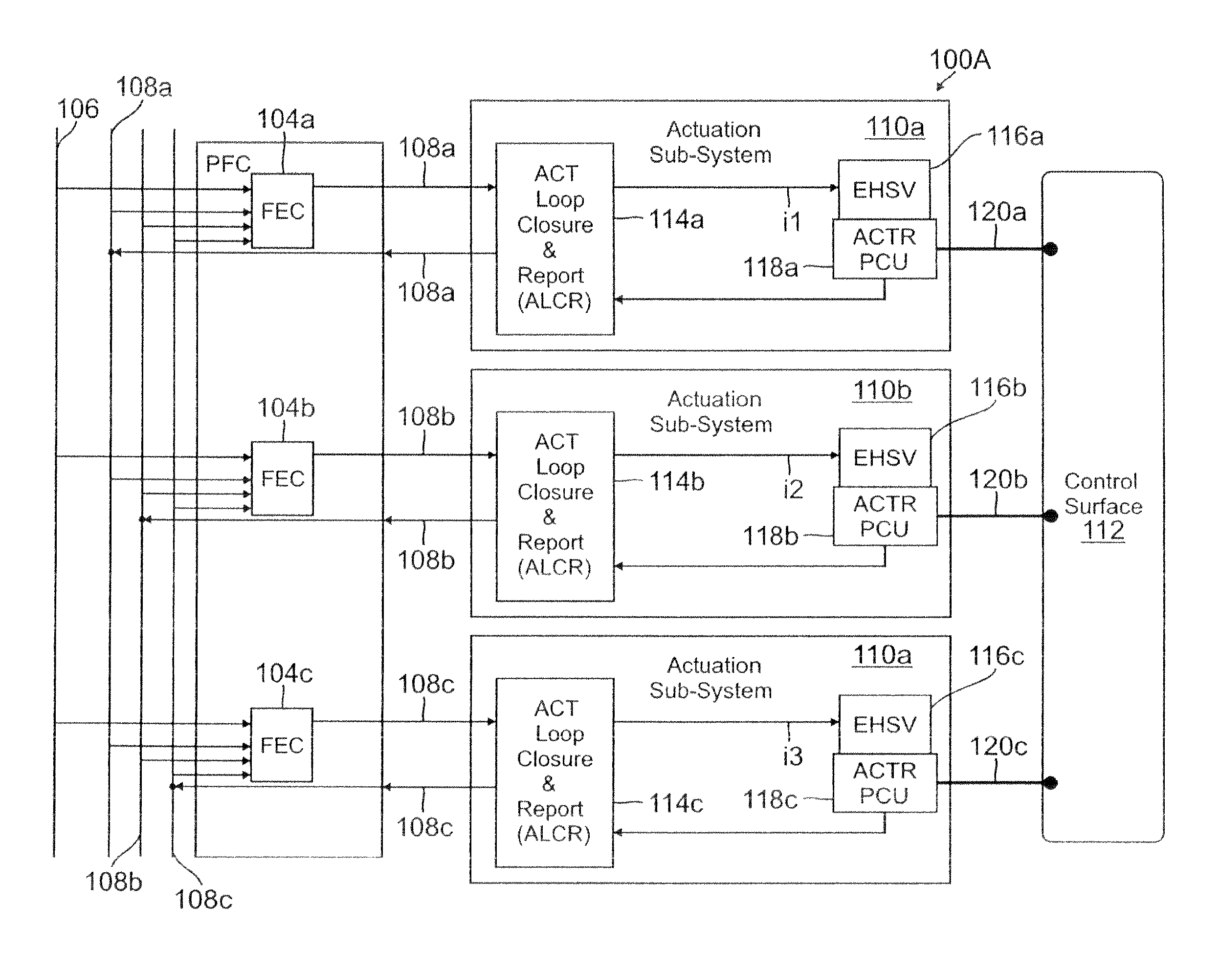
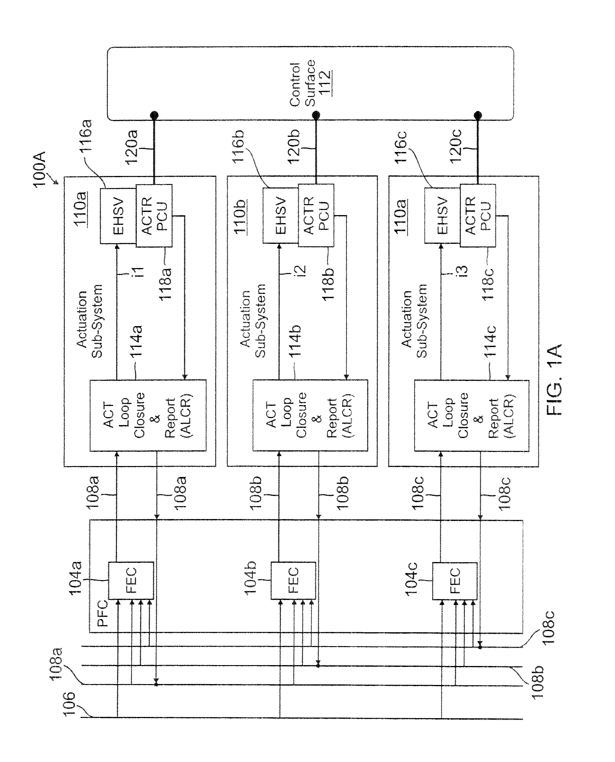
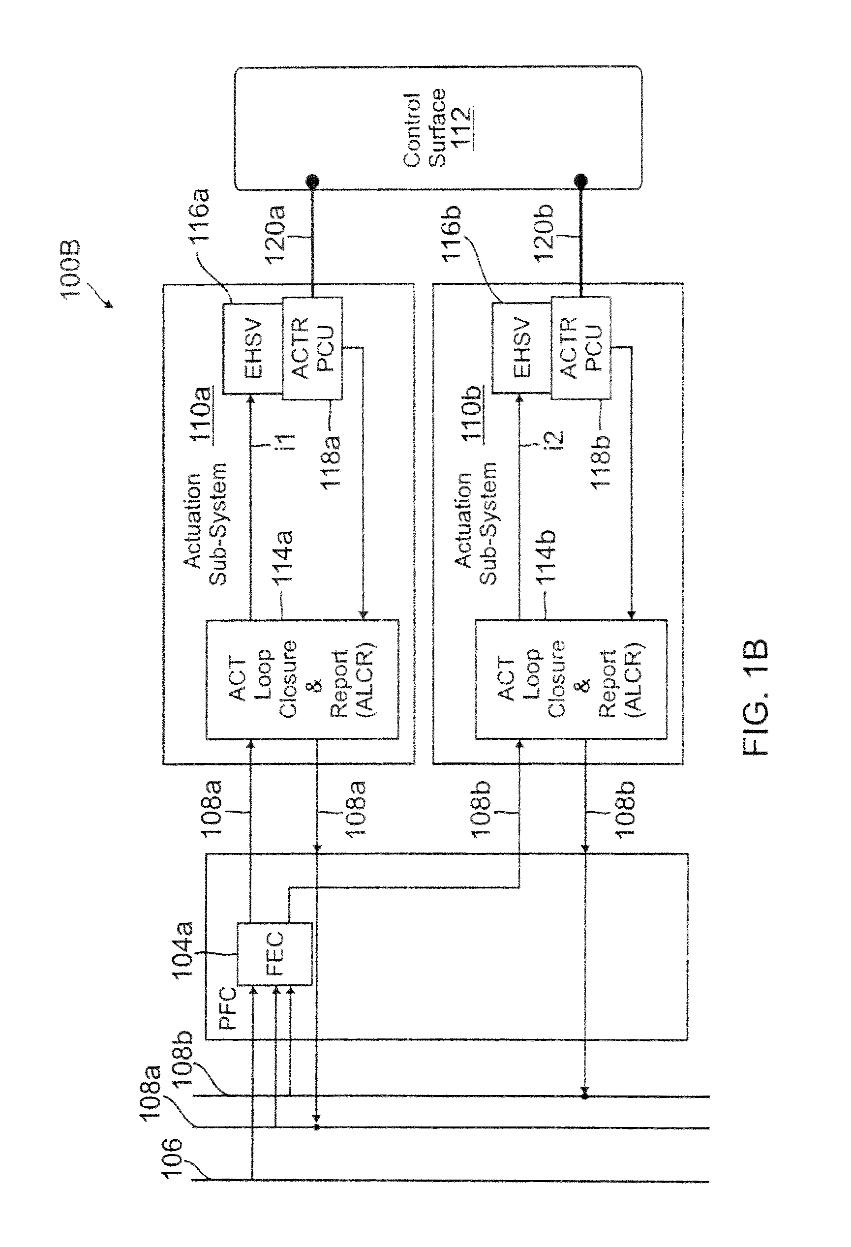
[0023]Generally, on control surfaces the applied forces that may cause fatigue occur because the structure is working against the intended load forces. For example, the actuators in a multiple actuator actuation system are not always properly positioned to share the intended load. In some instances, difference in actuator positioning may create a reactive force. These conditions are examples of “force fight.”

[0024]Generally, force equalization controllers sense the pressure difference across each of the hydraulic actuator pistons to determine the applied force per piston. The difference in actuator forces is then used, to identify the portion of the actuator force that may be attributed to force fight. The actuator force fight is then converted to a change in the position command for each actuator that ideally eliminates the force fight. The change in actuator position command is passed through a dead zone function to prevent limit cycles due to actuator friction and command path qu...


PUM


Abstract

An actuation system including a plurality of actuators; a plurality of position sensors coupled to the actuators, the plurality of position sensors providing rate feedback signals proportional to an actuator rate; a plurality of force sensors coupled to the actuators, the plurality of force sensors providing delta pressure signals; and a feedback control loop configured to receive the rate feedback signals and delta pressure signals and compute a difference in actual actuator rates and sum the difference with a computed difference in actuator forces to generate actuator positioning commands that equalize the actuator forces on a control surface.

Description

BACKGROUND[0001]1. Technical Field[0002]The present description relates to airplane actuation systems and, more particularly, to flight control actuator force equalization.[0003]2. Related Art[0004]Flight control systems have been the object of much effort directed toward enhancing the reliability and survivability of aircraft during flight.[0005]Generally, commands are translated into electrical signals through the use of transducers that sense the inputs. The electrical signals produced by the transducers are fed to a flight computer, along with other data indicative of flight parameters. Based upon the data it receives, the flight computer generates signals designed to achieve the desired flight path commanded. These signals are transmitted electrically, in typical control systems, to actuator controller units.[0006]The traditional problem encountered by aircraft flight control surfaces having multiple actuators is the ability to ensure that the actuators are positioned at relati...

Claims


Application Information

Patent Timeline
Patent Type & Authority Patents(United States)
IPC IPC(8): B64C13/16
CPCB64C13/42B64C13/503Y02T50/44Y02T50/40
Inventor KIRKLAND, DOUGLAS B.
Owner THE BOEING CO
Why Eureka
Try Eureka