Medical manipulator system

a technology of manipulator and manipulator body, which is applied in the direction of surgical staples, osteosynthesis devices, surgical instrument supports, etc., can solve the problems of inability to directly detect the position or origin of the pulleys disposed in the distal-end working unit and the rear end of the working uni

Active Publication Date: 2012-08-21
KARL STORZ GMBH & CO KG
View PDF11 Cites 808 Cited by
  • Summary
  • Abstract
  • Description
  • Claims
  • Application Information

AI Technical Summary

Benefits of technology

[0018]It is one of the objects of the present invention to provide a medical manipulator system which is capable of appropriately controlling a resetting process for actuators.

Problems solved by technology

The working unit does not include electronic devices such as sensors or the like because it should easily be cleaned and sterilized, and is incapable of directly detecting the positions or origins of the pulleys disposed in the distal-end working unit and the rear end of the working unit.
However, since the resetting process is a forcible process that is not performed normally, it should not be activated carelessly.

Method used


Image

  • Medical manipulator system
  • Medical manipulator system
  • Medical manipulator system

Examples


Embodiment Construction

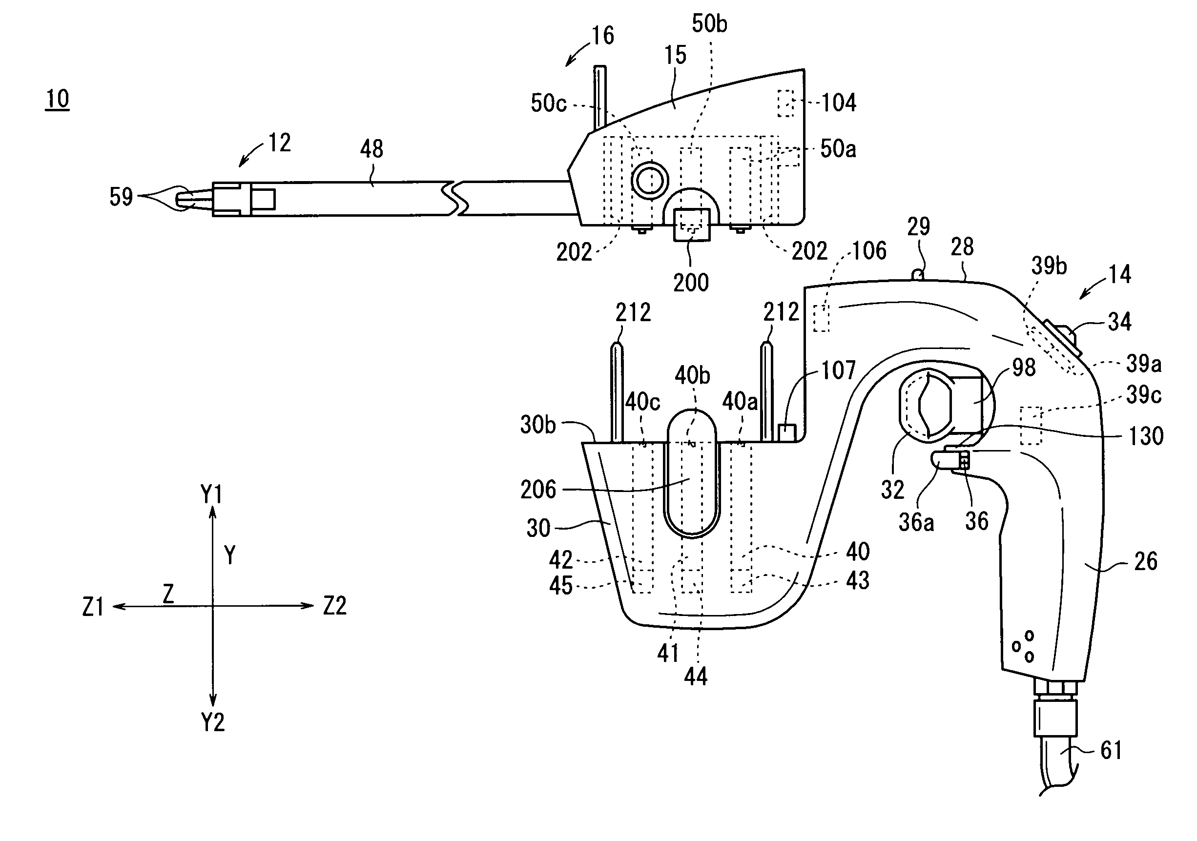
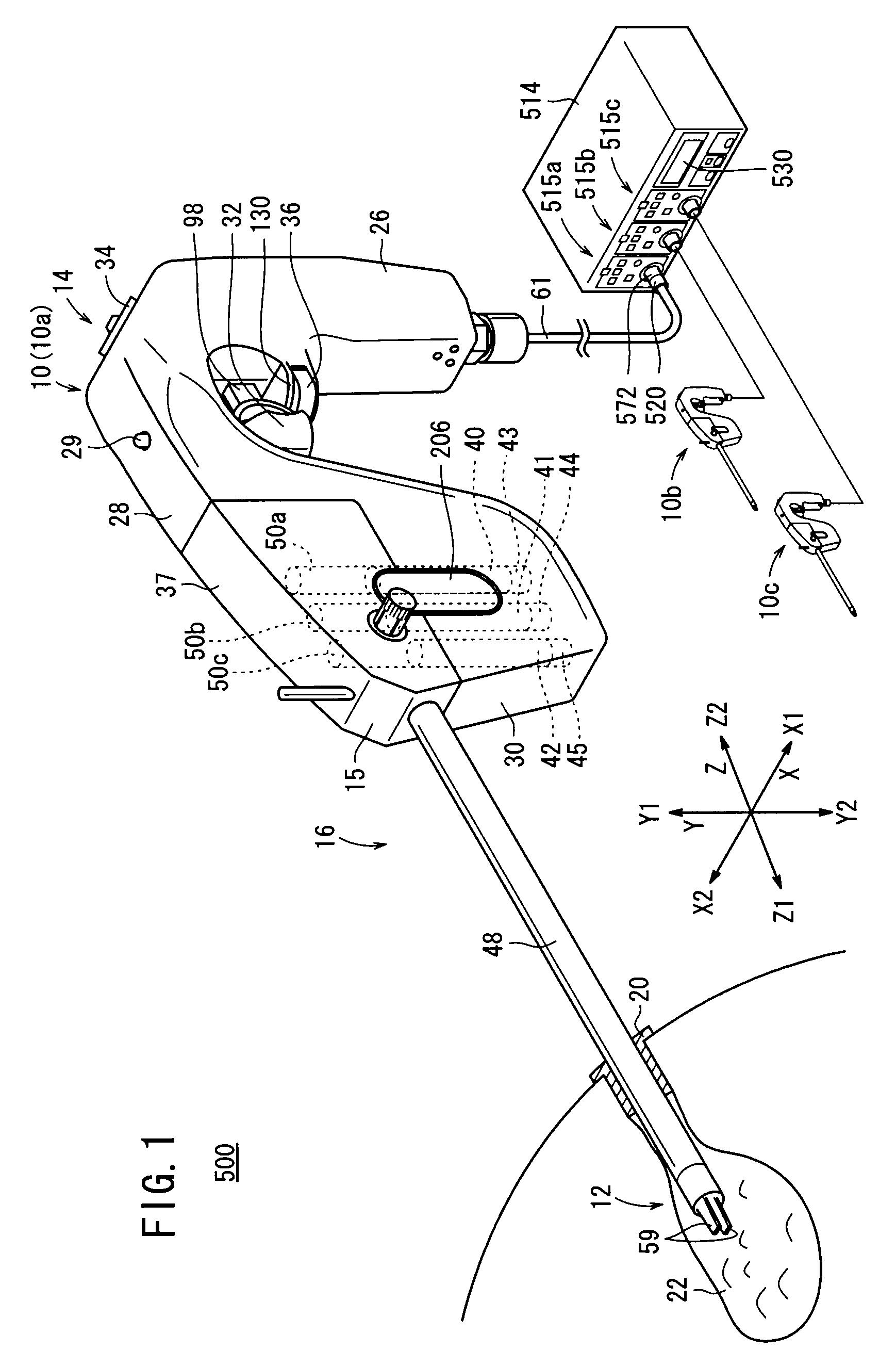
[0033]A medical manipulator system 500 according to an embodiment of the present invention will be described below with reference to FIGS. 1 through 11. The medical manipulator system 500 (see FIG. 1) is used in a laparoscopic surgical operation process or the like.

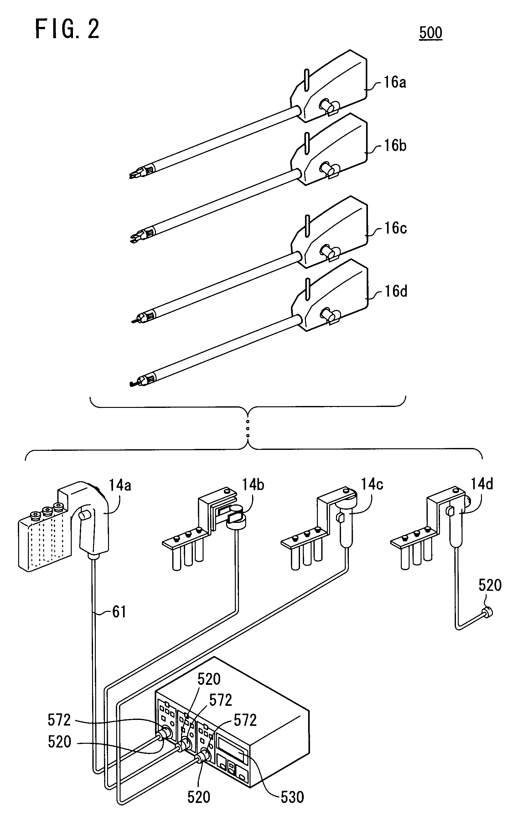
[0034]As shown in FIG. 1, the medical manipulator system 500 comprises a manipulator 10 and a controller 514.

[0035]The manipulator 10 and the controller 514 are detachably connected to each other by a connector 520.

[0036]The manipulator 10 has a distal-end working unit 12 for gripping a portion of a living tissue, a curved needle, or the like for performing a certain surgical treatment. The manipulator 10 comprises an operating unit 14 and a working unit 16 as basic components. The controller 514 electrically controls the manipulator 10, and is connected by a connector 520 to a cable 61 extending from the lower end of a grip handle 26 of the operating unit 14.

[0037]The controller 514 is capable of independently controllin...


PUM


Abstract

A medical manipulator system includes a manipulator, an operating unit for entering operation commands, motors for actuating a working unit, and a controller for energizing the motors based on operation commands supplied from the operating unit. When an activation resetting switch and a resetting switch are operated according to a predetermined procedure, the controller performs a resetting process to return the motors to an origin. The controller is capable of controlling three manipulators. The activation resetting switch is shared by the three manipulators, and there are three resetting switches corresponding to the three manipulators.

Description

BACKGROUND OF THE INVENTION[0001]1. Field of the Invention[0002]The present invention relates to a medical manipulator system including a working unit which is operable on the basis of an operation command input from an operating unit.[0003]2. Description of the Related Art[0004]In laparoscopic surgery, a number of small holes are opened in a patient's abdomen or the like, and an endoscope, a forceps (or manipulator) or the like is inserted, and surgery is carried out while the surgeon observes an image from the endoscope on a monitor. In this type of laparoscopic surgery, owing to the fact that opening of the abdominal cavity is unnecessary, the burden on the patient is small, and the number of days required for the post-operative recovery and the number of days spent in the hospital can be significantly reduced. Therefore, laparoscopic surgical operations are expected to find an increased range of applications.[0005]As disclosed in JP 2004-105451 A, for example, a manipulator syst...

Claims


Application Information

Patent Timeline
Patent Type & Authority Patents(United States)
IPC IPC(8): A61B17/94A61B19/00
CPCA61B19/22A61B19/26A61B2017/00199A61B2019/2242A61B34/70A61B34/71A61B90/50
Inventor OMORI, SHIGERUNAGASHIMADA, MASARUJINNO, MAKOTOSUNAOSHI, TAKAMITSU
Owner KARL STORZ GMBH & CO KG
Why Eureka
Try Eureka