
Semiconductor device having capacitors fixed to support patterns and method for manufacturing the same

a technology of capacitors and capacitors, which is applied in the direction of semiconductor devices, capacitors, electrical apparatus, etc., can solve the problems of compromising the integrity (i.e., cracks and alike) of the resultant micro-sized cylindrical capacitors, and physical limitations or barriers exist, so as to prevent or at least minimize the occurrence of cracks

Active Publication Date: 2012-08-21
SK HYNIX INC
View PDF10 Cites 0 Cited by
  • Summary
  • Abstract
  • Description
  • Claims
  • Application Information

AI Technical Summary

Benefits of technology

[0011]Embodiments of the present invention are directed to a semiconductor device that can prevent or at least minimize the occurrence of cracks and alike from occurring between the support pattern and the storage nodes. Embodiments of methods for manufacturing the same are also presented.
[0012]Also, embodiments of the present invention are directed to a semiconductor device that can prevent or minimize leakage of the resultant capacitor semiconductor device. Thereby the embodiments of the present invention contribute to improving the operational characteristics of these types of capacitor semiconductor devices.

Problems solved by technology

In this regard, physical limitations or barriers exist when trying to decrease the distance between electrodes.
However, a number of difficulties in fabricating micro sized cylindrical capacitors can occur.
In particular, forming the cylindrical type capacitors using a dip-out process to remove the mold insulation layer that serves as a mold for forming storage nodes can result in compromising the integrity (i.e., cracks and alike) of the resultant micro-sized cylindrical capacitors.
As a result of conducting the dip-out process, these micro-sized cylindrical capacitors are prone to leaning.
However, in the conventional art as described above, the stress induced when conducting the dip-out process and subsequently forming the dielectric layer to the support patterns contributes to cracks between the support patterns and the storage nodes.
As a result, leakage of capacitance is can result which degrades the operational characteristics of a semiconductor devices.

Method used


Image

  • Semiconductor device having capacitors fixed to support patterns and method for manufacturing the same
  • Semiconductor device having capacitors fixed to support patterns and method for manufacturing the same
  • Semiconductor device having capacitors fixed to support patterns and method for manufacturing the same

Examples


Embodiment Construction

[0031]Hereafter, specific embodiments of the present invention will be described in detail with reference to the accompanying drawings.

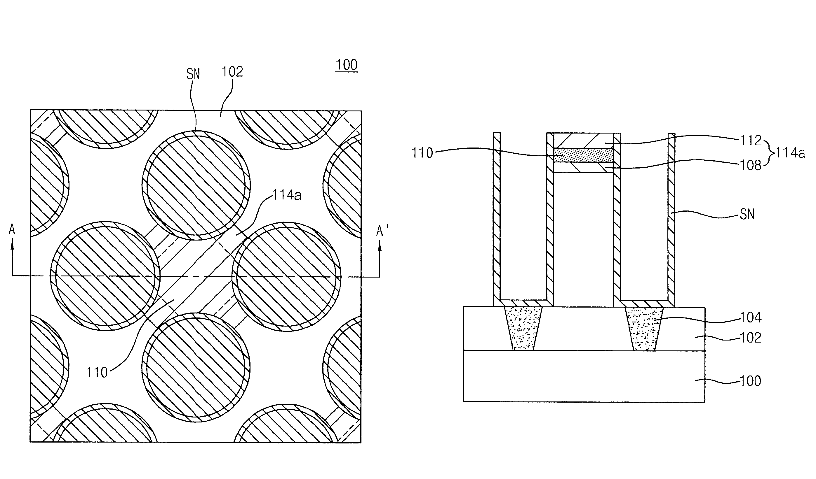
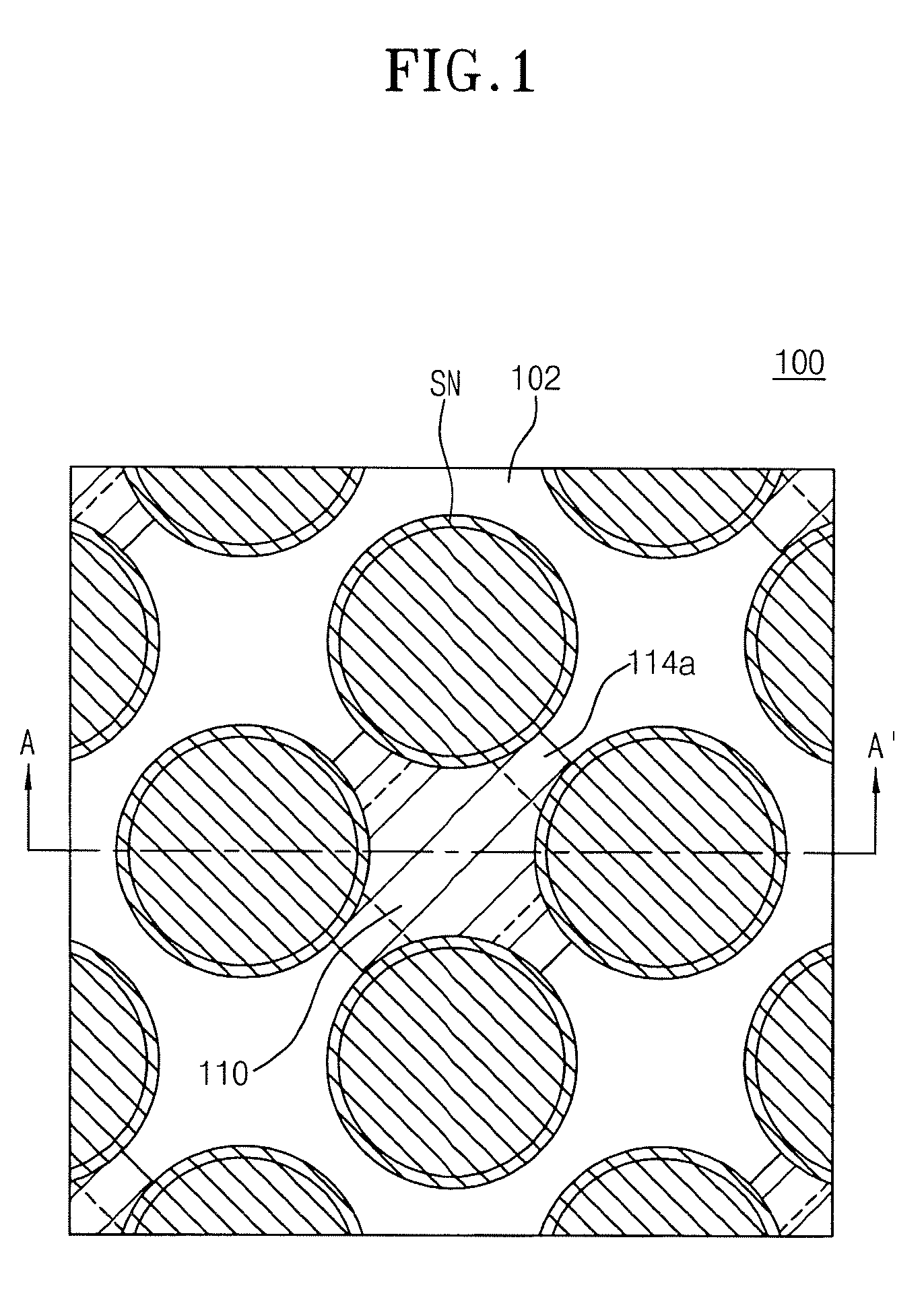
[0032]FIG. 1 is a plan view showing a semiconductor device in accordance with one embodiment of the present invention.

[0033]Referring to FIG. 1, an interlayer dielectric 102 is formed over a semiconductor substrate 100, and a plurality of cylinder type storage nodes SN are formed on the interlayer dielectric 102. Support patterns 114a are formed to fix or buttress together adjacent storage nodes SN. Each support pattern 114a has a structure in which a flowable insulation layer 110 for contacting the storage nodes SN is inserted.

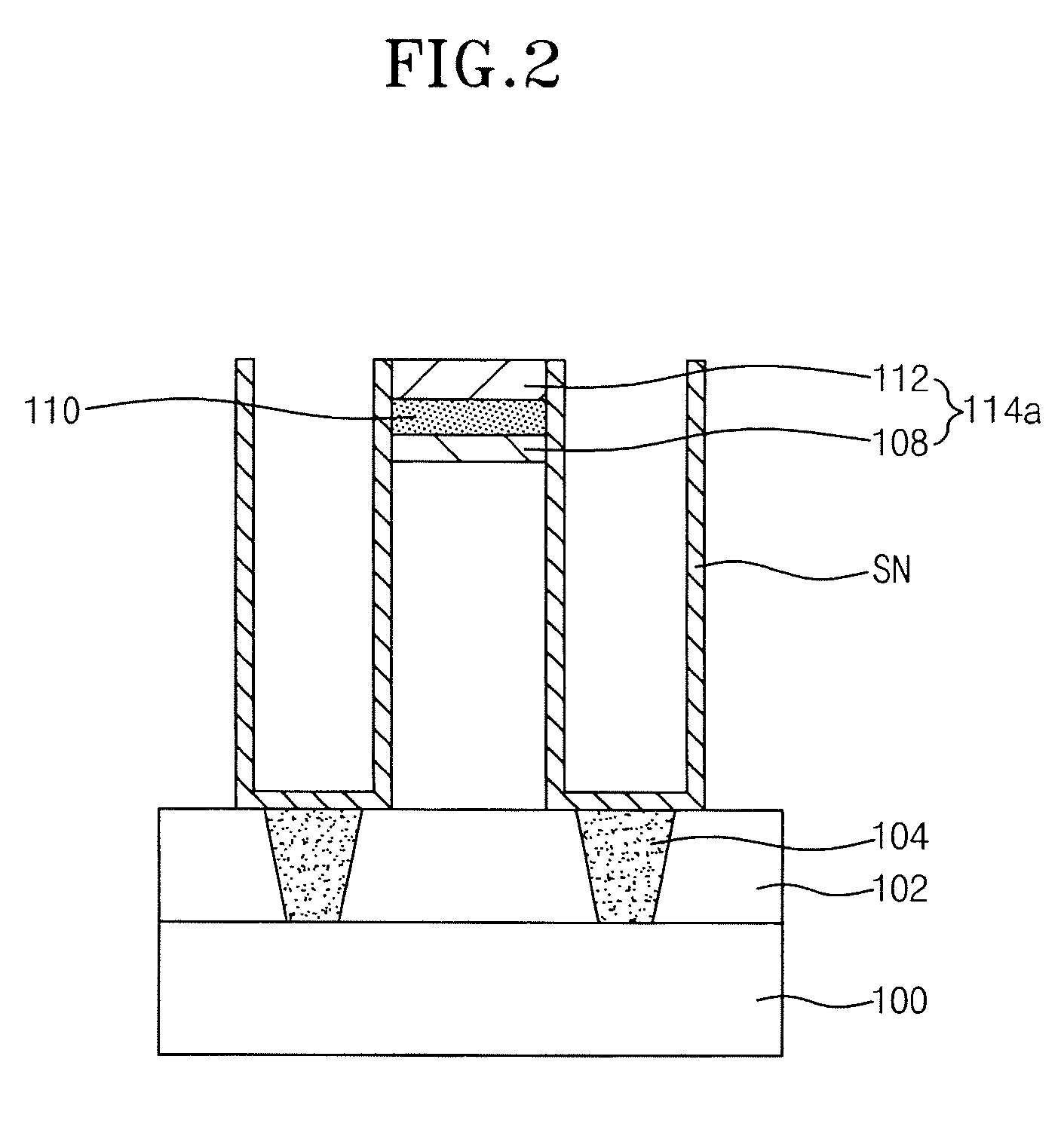
[0034]FIG. 2 is a sectional view taken along the line A-A′ of FIG. 1, illustrating the semiconductor device in accordance with one embodiment of the present invention.

[0035]Referring to FIG. 2, the interlayer dielectric 102 is formed over the semiconductor substrate 100, and a plurality of storage node contact plugs 104 is for...


PUM


Abstract

A semiconductor device containing a cylindrical shaped capacitor and a method for manufacturing the same is presented. The semiconductor device includes a plurality of storage nodes and a support pattern. The plurality of storage nodes is formed over a semiconductor substrate. The support pattern is fixed to adjacent storage nodes in which the support pattern has a flowable insulation layer buried within the support pattern. The buried flowable insulation layer direct contacts adjacent storage nodes.

Description

CROSS-REFERENCE TO RELATED APPLICATIONS[0001]The present application claims priority to Korean patent application number 10-2008-0030345 filed on Apr. 1, 2008, which is incorporated herein by reference in its entirety.BACKGROUND OF THE INVENTION[0002]The present invention relates generally to semiconductor devices and methods for manufacturing the same, and more particularly, to semiconductor devices that can prevent or at least minimize the occurrence of cracks and alike from occurring between a support pattern and storage nodes and methods for manufacturing the same.[0003]The demand for high performance semiconductor memory devices continues to rapidly increase. Accordingly, various techniques for obtaining small capacitors that have high capacitance are in demand. The fundamentals of exactly what is required to make a capacitor are relatively simple. A capacitor is an electronic structure that has a dielectric interposed between storage nodes and plate nodes. The capacitance of t...

Claims


Application Information

Patent Timeline
Patent Type & Authority Patents(United States)
IPC IPC(8): H01L27/10
CPCH01L28/90H01L27/10852H10B12/033H10B99/00H10B12/00
Inventor PARK, SUNG MIN
Owner SK HYNIX INC
Learn More