Electro-optical apparatus and electronic equipment

a technology of electro-optical apparatus and electronic equipment, applied in the field of electro-optical apparatus, can solve the problems of reduced observation range of observers, image appears dark, disadvantageous shielding of part of light outputted from the image display surface, etc., and achieve the effect of improving the display quality of electro-optical apparatus

Active Publication Date: 2012-08-21
EPSON IMAGING DEVICES CORP +1
View PDF12 Cites 10 Cited by
  • Summary
  • Abstract
  • Description
  • Claims
  • Application Information

AI Technical Summary

Benefits of technology

[0009]An advantage of some aspects of the invention is to improve the display quality of an electro-optical apparatus as described above.
[0011]The electro-optical apparatus is, for example, an image display apparatus for achieving two-screen display or stereoscopic image display, and includes the display panel, the illuminating device, the polarization axis controlling unit, and the lens having a plurality of linear-shaped lens patterns. The display panel displays an image. The illuminating device is so-called back light, and allows the light rays to pass through the display panel. The polarization axis controlling unit is, for example, a polarization controlling liquid crystal panel, and allows the light rays having the first polarization axis out of the light rays emitted from the illuminating device to pass and changing the polarization axes of the part of the light rays emitted from the illuminating device to convert the light rays to light rays having the second polarization axis different from the first polarization axis. The lens having the plurality of linear-shaped lens patterns is, for example, a lenticular lens, which is arranged between the polarization axis controlling unit and the display panel for causing the light rays having the first polarization axis and the light rays having the second polarization axis separated by the polarization axis controlling unit to proceed in the predetermined directions respectively. The polarization axis controlling unit includes the liquid crystal layer and the plurality of electrodes arranged in a stripe pattern so as to oppose the liquid crystal layer and, out of the plurality of electrodes which correspond to one of the lens patterns, the width of the electrodes to which a voltage is applied when changing the polarization axis of the part of the light rays out of the light rays emitted from the illuminating device is formed to be larger than the width of the electrodes to which no voltage is applied. The area from which the polarized light rays can be outputted can be increased by using such polarization axis controlling unit than using the polarization axis controlling unit in which the width of the electrodes to which the voltage is applied is the same as the width of the electrodes to which no voltage is applied. Accordingly, the output direction of the light rays having the first polarization axis and the light rays having the second polarization axis from the polarization axis controlling unit can be adjusted appropriately, and hence the quality of display can be adjusted appropriately.
[0013]According to an aspect of the invention, in the electro-optical apparatus shown above, the sets of electrodes including the electrode to which the voltage is applied and the electrode to which no voltage is applied are provided so that each set corresponds to each one of the lens patterns. Accordingly, when presenting different images to the observers at different observing positions in the two-screen display mode, the boundary between the images is prevented from being shifted from the center of the display screen, that is, the position of the boundary between the observation ranges of the observers at the different observing positions is prevented from being shifted from the center of the display screen. Simultaneously, ingress of the image to be presented to one of the observer partly into the observation range of the other observer can be prevented.
[0015]According to another aspect of the invention, in the electro-optical apparatus, the sets of the electrodes including an electrode to which the voltage is applied and an electrode to which no voltage is applied are provided so that two sets each correspond to each one of the lens patterns. Accordingly, the position of the boundary between the observation ranges of the observers at different observing positions is prevented from being shifted from the center of the display screen in the stereoscopic image display mode. The position on the display screen to be placed at the center between the eyes of the observer for viewing the stereoscopic display image can be placed to a position close to the center of the observation range of the observer

Problems solved by technology

Therefore, part of the light outputted from the image display surface is disadvantageously shielded by the shielding portions of the electronic parallax barrier.
Consequently, there arises a problem such that the image appears to be dark since the luminance of the image observed by the observer is too low.
In the image display apparatus which can achieve the two-screen display in the related art, there is a problem such that it has a property that the observation range of the observer is proportional to one pixel pitch of the display panel, and hence when the pixel pitch is lowered, the observation range of the observer is also decreased, which makes provision of a high quality image to observers at different observing positions difficult.
However, there is a problem in the image display apparatus using the lenticular lens such that in the case of the two-screen display, the boundary between two images may be shifted from the center of the display screen when presenting the different images to the observers at the different observing positions.
There is also a problem such that part of the image to be presented to one observer may be intermixed with an image to be presented to the other observer.

Method used


Image

  • Electro-optical apparatus and electronic equipment
  • Electro-optical apparatus and electronic equipment
  • Electro-optical apparatus and electronic equipment

Examples


first embodiment

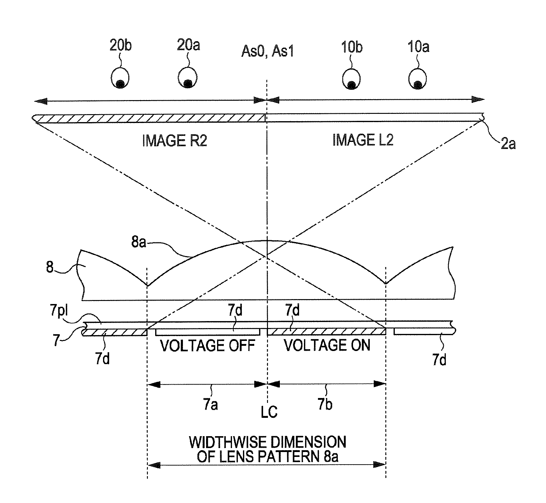
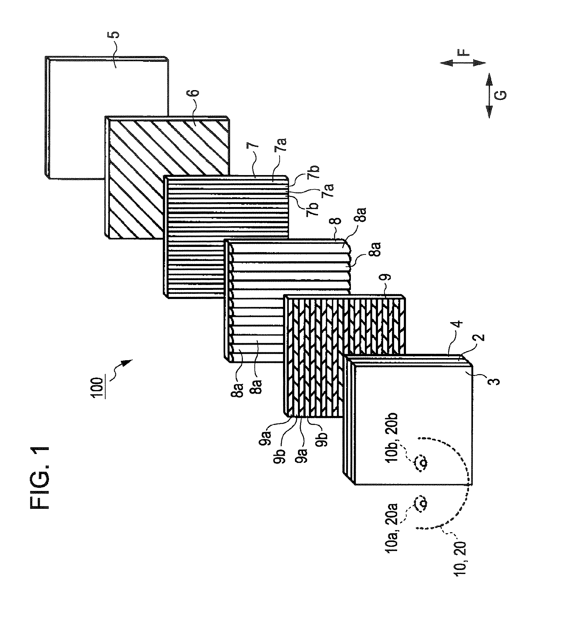
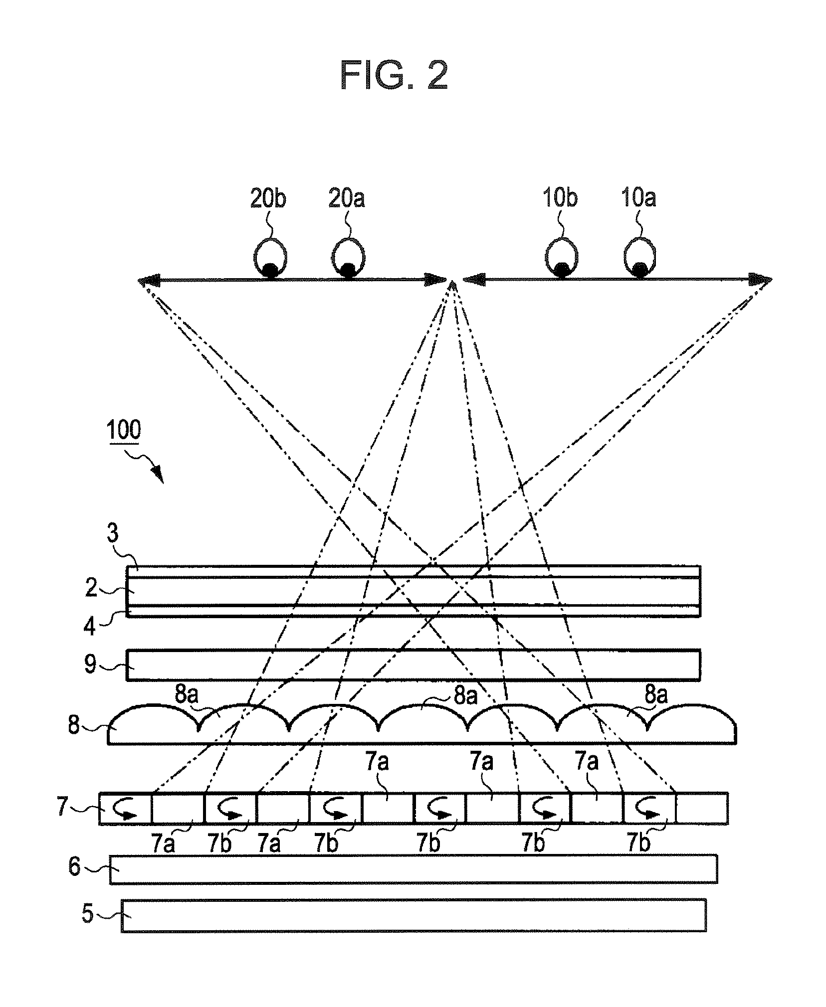
[0035]FIG. 1 is an exploded perspective view showing an image display apparatus 100 according to a first embodiment of the invention. The image display apparatus 100 according to the first embodiment achieves two-screen display that presents different images to a plurality of observers at different observing positions. FIG. 2 is an explanatory drawing showing a principle of the image display apparatus 100 according to the first embodiment of the invention shown in FIG. 1 in a state in which an observer views the display panel from above. FIG. 3 is a partly enlarged drawing of a polarization controlling liquid crystal panel of the image display apparatus 100 according to the first embodiment of the invention shown in FIG. 1. FIG. 4 is an explanatory drawing showing a principle of the image display apparatus 100 according to the first embodiment of the invention shown in FIG. 1 in a state in which the observer views the image display apparatus 100 from the side. FIG. 5 is an exploded ...

second embodiment

[0063]Subsequently, the image display apparatus 100 according to a second embodiment of the invention will be described. The image display apparatus 100 according to the second embodiment achieves stereoscopic image display that presents three-dimensional stereoscopic image. The configuration of the image display apparatus 100 according to the second embodiment is almost the same as the configuration of the image display apparatus 100 according to the first embodiment. However, the structure of the polarization controlling area 7a and the polarization controlling area 7b in the polarization controlling liquid crystal panel 7 is different. That is, the structure of the polarization controlling liquid crystal panel in the image display apparatus 100 according to the second embodiment has a different structure from the structure shown in FIG. 3. FIG. 10 is a partially enlarged view of the polarization controlling liquid crystal panel according to the image display apparatus 100 accordi...

example of application

[0089]In the respective embodiments shown above, the plurality of semi-column shaped lens patterns are formed in the lenticular lens 8 so as to extend toward the display panel. However, the direction of the semi-column shaped lens pattern is not limited thereto, and may be formed so as to extend in the opposite direction from the display panel, that is, the plurality of lens patterns 8a may be formed so as to extend toward the polarization controlling liquid crystal panel. Instead of the lenticular lens 8, a lens having linear lens pattern having other cross-sectional shape, for example, a plurality of lens patterns being triangular instead of semi-column shape in cross section may be used.

[0090]In the embodiments shown above, the lenticular lens 8 is an independent component in the image display apparatus 100. However, the configuration of the lenticular lens 8 is not limited thereto and, instead, one of the pair of substrates of the polarization controlling liquid crystal panel 7 ...


PUM

PropertyMeasurementUnit
distanceaaaaaaaaaa
distanceaaaaaaaaaa
widthaaaaaaaaaa

Abstract

An electro-optical apparatus includes a display panel that displays an image, an illuminating device that allows light rays to pass through the display panel, a polarization axis controlling unit arranged between the illuminating device and the display panel for allowing light rays having first polarization axis out of light rays outputted from the illuminating device to pass and changing the polarization axes of part of the light rays emitted from the illuminating device to convert the light rays to light rays having second polarization axis different from the first polarization axis, and a lens having a plurality of linear lens patterns for causing the light rays having the first polarization axis and the light rays having the second polarization axis separated by the polarization axis controlling unit respectively to proceed in predetermined directions. The polarization axis controlling unit includes a liquid crystal layer and a plurality of electrodes arranged in a stripe pattern so as to oppose the liquid crystal layer. The width of the electrodes to which a voltage is applied when changing the polarization axes of the part of the light rays emitted from the illuminating device is larger than the width of the electrode to which no voltage is applied.

Description

BACKGROUND[0001]1. Technical Field[0002]The present invention relates to an electro-optical apparatus suitable for displaying various types of information, and electronic equipment.[0003]2. Related Art[0004]Examples of an electro-optical apparatus are an image display apparatus such as a stereoscopic image display apparatus for displaying a three-dimensional stereoscopic image and a two-screen display device that displays different images for observers at different observing positions. In Japanese Patent No. 2857429, an image display apparatus which can achieve stereoscopic display of a parallax barrier system is described as one of the systems of the stereoscopic display apparatus which can display a three-dimensional stereoscopic image. In this image display apparatus, predetermined shaped openings and light-shielding portions are arranged in a stripe pattern at predetermined positions of an electronic parallax barrier by controlling the electronic parallax barrier arranged on the...

Claims


Application Information

Patent Timeline
Patent Type & Authority Patents(United States)
IPC IPC(8): G02B27/22G02F1/1335G02B30/25
CPCG02F1/13471H04N13/0411H04N13/0418H04N13/0447G02F1/133526G02F2001/133638G02F2413/09G02F1/133631G02F1/133638H04N13/312H04N13/32H04N13/351
Inventor SUGIYAMA, NOBUO
Owner EPSON IMAGING DEVICES CORP
Why Eureka
Try Eureka