Bottom up contact type ultrasonic continuous level sensor

a technology of ultrasonic continuous level sensor and contact type, which is applied in the direction of level indicators, measurement devices, instruments, etc., can solve the problems of adding expense to the construction of the vessel, /b> being unable to measure the liquid level to or close to the bottom of the vessel, and its mounting difficulty

Active Publication Date: 2012-08-21
MEASUREMENT SPEC
View PDF17 Cites 22 Cited by
  • Summary
  • Abstract
  • Description
  • Claims
  • Application Information

AI Technical Summary

Problems solved by technology

But this adds expense in the construction of the vessel and can make its mounting more difficult.
Another disadvantage is that a characteristic of PZT material is such that it “rings” when an

Method used


Image

  • Bottom up contact type ultrasonic continuous level sensor
  • Bottom up contact type ultrasonic continuous level sensor
  • Bottom up contact type ultrasonic continuous level sensor

Examples


Embodiment Construction

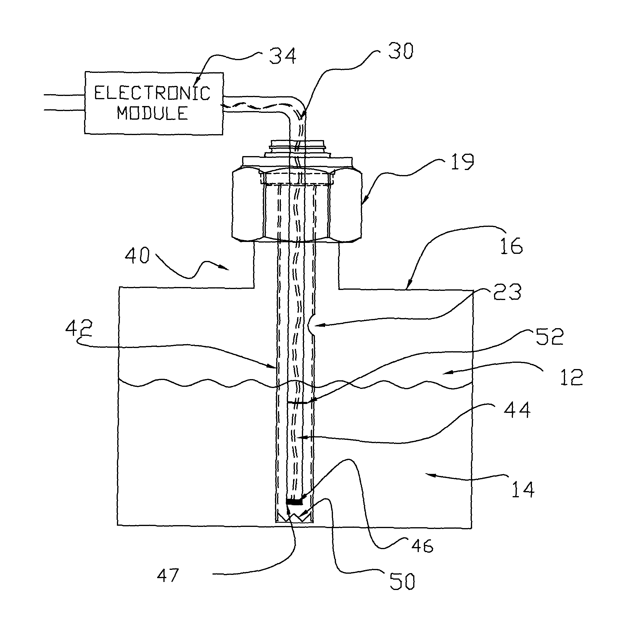
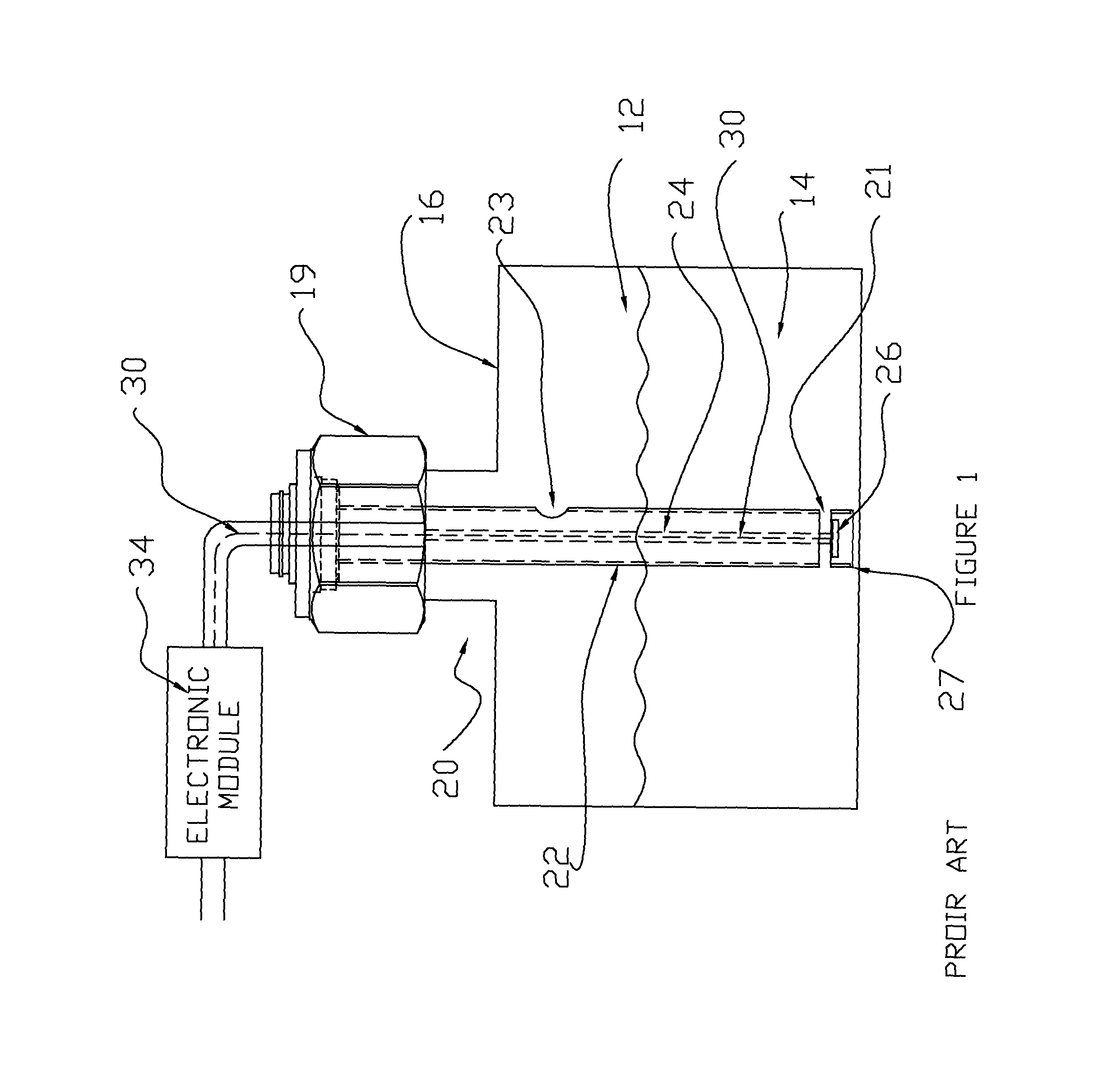
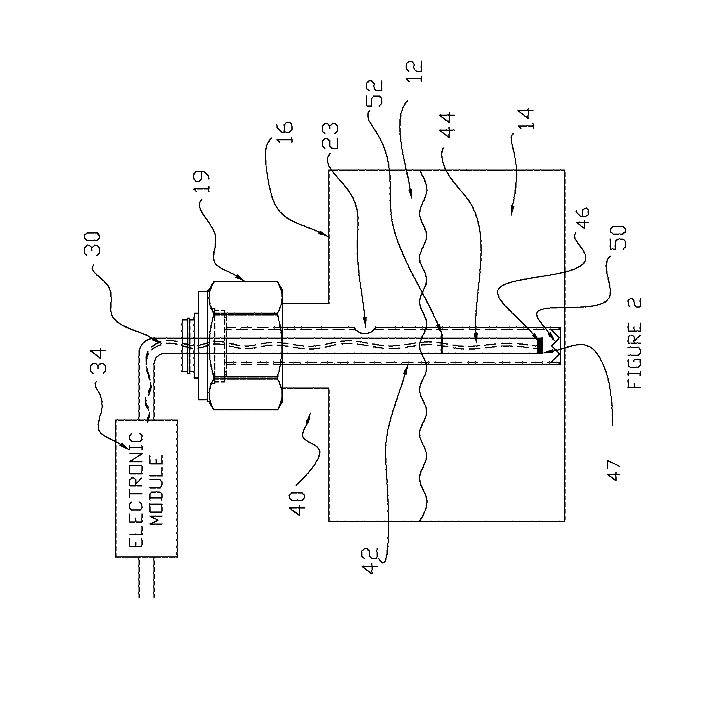
[0020]Referring to FIGS. 2 and 3, the same reference numbers are used for the same components as in FIG. 1. Here also there is vessel 12 having a top wall 16 that contains a liquid 14. A sensor 40 has a hollow tubular probe 42 suspended within the vessel from the header 19 mounted to the vessel top wall 16. The probe 42 is of any suitable material such as stainless steel or plastic and can be suspended in the vessel liquid by any suitable mounting arrangement. The probe 42 also has a vent hole 23.

[0021]A tube 44 extends from the header 19 within probe 42. The tube 44 also can be attached to an inner wall of the probe 42 by suitable spacers or supports. The tube 44 also is of a suitable material such as stainless steel or plastic.

[0022]A transducer 46, preferably a PZT (lead-zirconate-titanate) or PVDF (polyvinylidene fluoride) piezoelectric crystal, is in or on a housing 47 or plate that is mounted to tube 44 near its lower end. The transducer housing or plate 47, which is of a mate...


PUM


Abstract

An ultrasonic sensor for measuring the level of liquid in a vessel has an elongated tubular probe, a tube within the probe, and a transducer that converts electrical energy to ultrasonic energy mounted at or near one end of the tube to transmit ultrasonic energy along the probe longitudinal axis. A conical reflector that reflects ultrasonic energy is opposite the transducer ultrasonic energy emitting part to reflect ultrasonic energy received from the transducer upwardly in the probe to an air-liquid interface from which it is downwardly reflected to the conical reflector element that directs the energy reflected from the interface back to the transducer for conversion to an electrical signal that is used by an electronic module to measure the liquid level in the probe, which is the liquid level in the vessel, by measuring the round trip travel time of the ultrasonic signal energy.

Description

FIELD OF THE INVENTION[0001]The invention is directed to a bottom up ultrasonic sensor that provides continuous detection of liquid level within a vessel with a reduced dead zone of measurement at the vessel bottom.BACKGROUND OF THE INVENTION[0002]Ultrasonic sensors for continuously or intermittently measuring the level (height) of a liquid within a vessel are well known. The liquid can be of any type including different types of chemical and high purity liquids used in the manufacture of semiconductors. Such sensors have a transducer located close to the bottom wall of the vessel that transmits a beam of ultrasonic energy upwardly to the liquid surface. The sensor transducer is most often mounted at the bottom end of an elongated probe that extends within the vessel and that contains the liquid at the same height level as it is in the vessel. The ultrasonic energy is transmitted from the bottom end of the probe and is reflected from the liquid surface and received back at the trans...

Claims


Application Information

Patent Timeline
IPC IPC(8): G01S15/00
CPCG01S7/521G01S15/08G01F23/2962
Inventor ENZLER, GEORGE W.MELDER, GLEN D.
Owner MEASUREMENT SPEC
Why Eureka
Try Eureka