
Rotating mechanism for an electronic device and an electronic device with the same

a technology of electronic devices and rotating mechanisms, which is applied in the direction of mechanical control devices, instruments, and details of portable computers, etc., can solve the problems of limited rotation angle and the need to modify the rotating mechanism of electronic devices

Inactive Publication Date: 2012-08-28
KYE SYST CORP
View PDF6 Cites 6 Cited by
  • Summary
  • Abstract
  • Description
  • Claims
  • Application Information

AI Technical Summary

Benefits of technology

Enables increased rotational flexibility and adjustability of electronic device components, enhancing their usability and appearance by allowing for a broader range of motion between the stationary and rotating shells.

Problems solved by technology

Therefore, the rotating angle is limited and the conventional rotating mechanism for the electronic device needs to be modified.

Method used


Image

  • Rotating mechanism for an electronic device and an electronic device with the same
  • Rotating mechanism for an electronic device and an electronic device with the same
  • Rotating mechanism for an electronic device and an electronic device with the same

Examples


Embodiment Construction

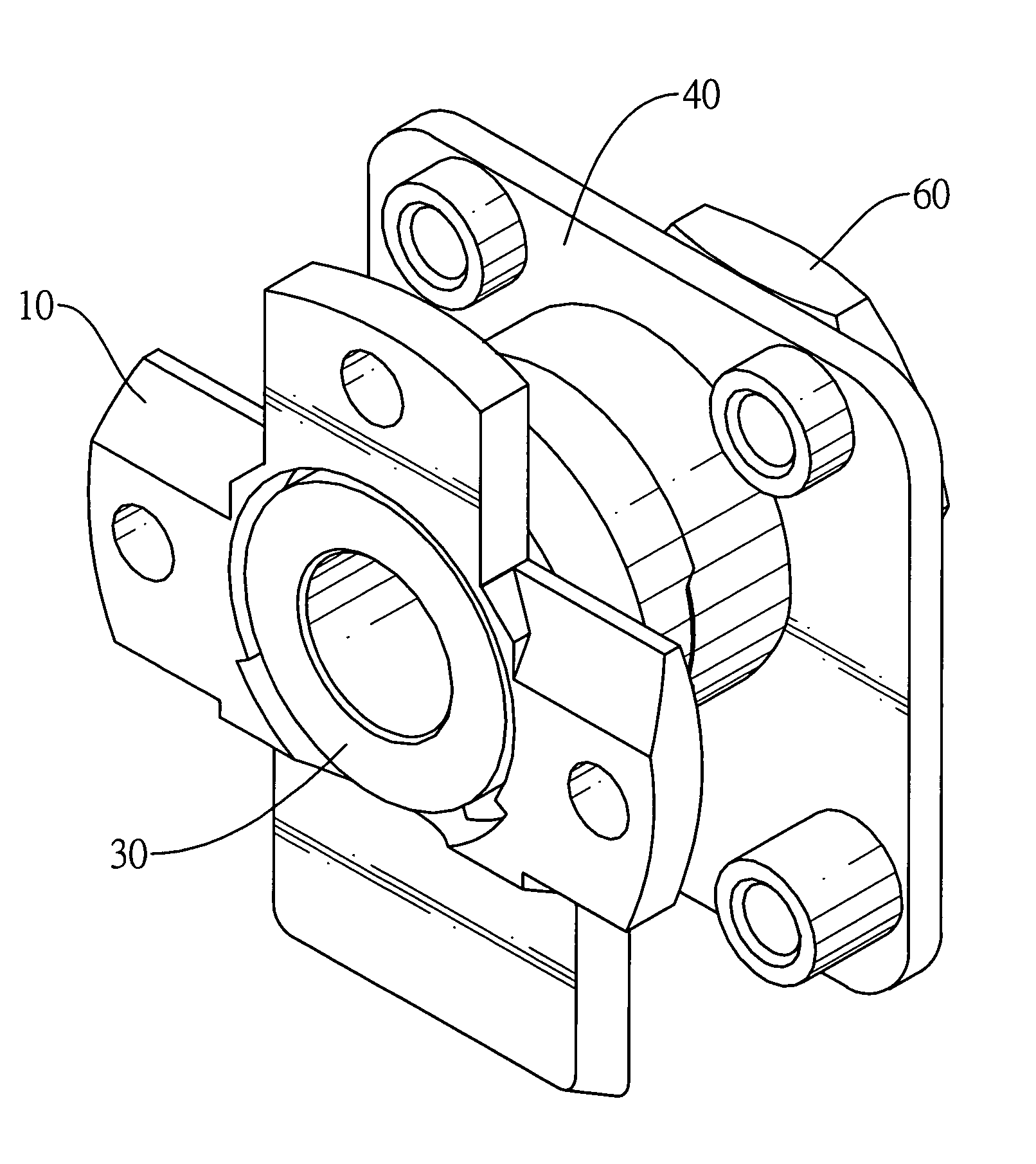
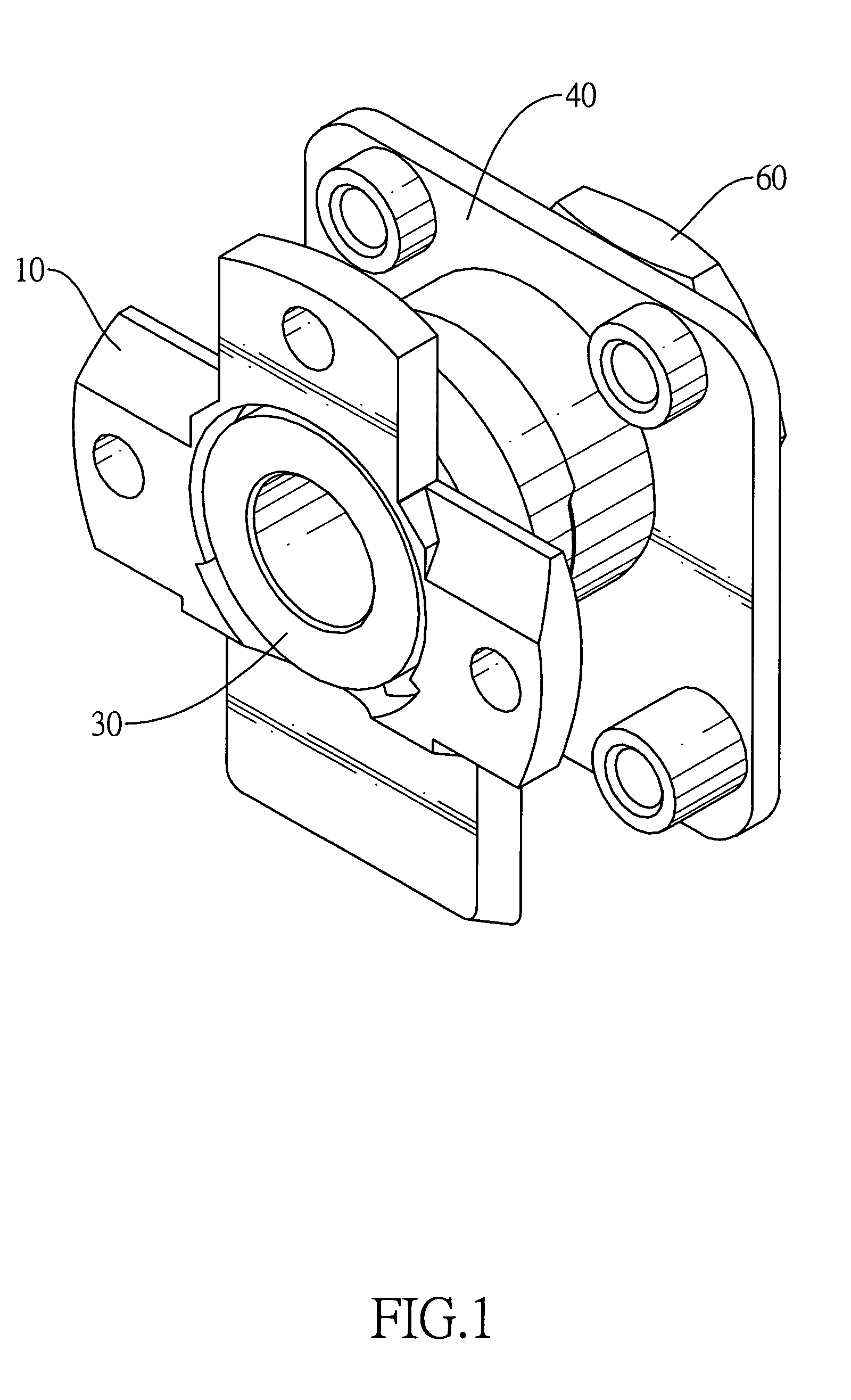
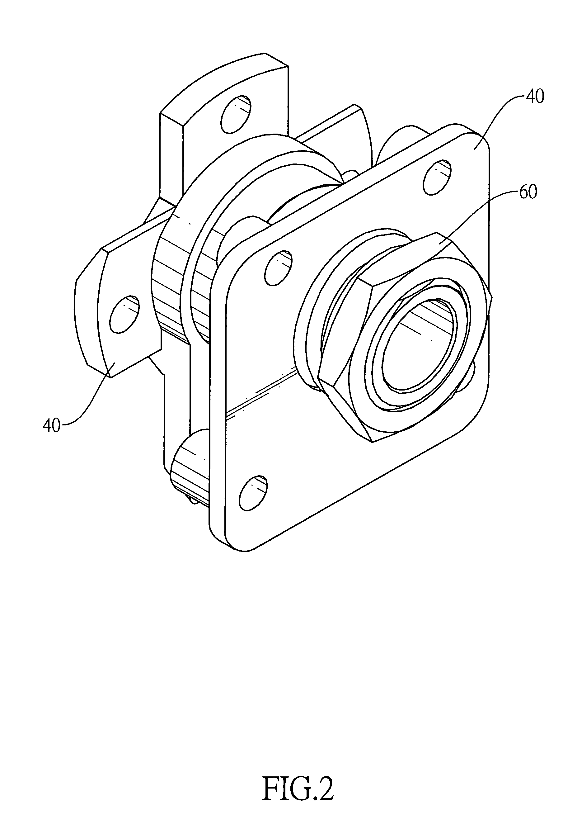
[0035]With reference to FIGS. 1 to 3, a rotating mechanism for an electronic device in accordance with the present invention comprises a stationary seat (10), a limiting ring (20), a shaft (30), a rotating seat (40), a resilient element and a fastening ring (60).

[0036]With reference to FIGS. 3 to 5, the stationary seat (10) has a stationary board (11) and a stationary sleeve (12). The stationary board (11) is hollow and has a limiting recess (111) formed transversely in an inside wall thereof. The stationary sleeve (12) protrudes axially from a face of the stationary board (11). The inner diameter of the stationary sleeve (12) is smaller than the inner diameter of the stationary board (11). A positioning assembly is formed on a free end of the stationary sleeve (12) and may be two positioning detents (121) opposite to each other.

[0037]With reference to FIGS. 3 and 6, the limiting ring (20) is mounted through the stationary seat (10) and abuts a connecting end of the stationary sleev...


PUM


Abstract

A rotating mechanism for an electronic device has a stationary seat with a limiting recess, a limiting ring mounted through the stationary seat with inner and outer limits, a shaft mounted through the stationary seat and the limiting ring with a limiting protrusion. With the limiting protrusion pushing the inner limit and the outer limit sliding in the limiting recess, the shaft achieves two stages of rotation to enhance the rotating angle in both directions. Moreover, with the adjusting of the sizes of the components, the rotating mechanism may provide rotating angle by 360 to 700 degrees.

Description

BACKGROUND OF THE INVENTION[0001]1. Field of the Invention[0002]The present invention relates to a rotating mechanism for an electronic device and an electronic device with the same, especially to a mechanism for various electronic devices to allow them pivoting.[0003]2. Description of the Prior Arts[0004]Electronic peripheral devices such as lens, joysticks and the like usually has a rotating mechanism mounted between two elements to allow pivoting and adjusting relating positions so that the electronic peripheral devices may have various usage.[0005]With reference to FIG. 16, a conventional rotating mechanism for an electronic device comprises a first casing (70) and a second casing (80). The casings (70, 80) are hollow and have electrical components to provide desired functions for the electronic device.[0006]The first casing (70) has a through hole formed through an end thereof and has a positioning resilient bar (71) and a positioning seat (72) mounted on beside the through hol...

Claims


Application Information

Patent Timeline
Patent Type & Authority Patents(United States)
IPC IPC(8): E05D11/10
CPCF16M11/06G06F1/1605G06F1/1681G06F1/1615F16M2200/024G05G2009/04703Y10T16/54038Y10T16/5385Y10T16/54Y10T16/540255
Inventor JOU, YU-TANG
Owner KYE SYST CORP
Learn More