Valve timing controller

a timing controller and valve technology, applied in the direction of drip or splash lubrication, machines/engines, couplings, etc., can solve the problems of deterioration in productivity or increase in productive cost, and achieve the effect of simple lubricating structure and improved lubrication property

Active Publication Date: 2012-08-28
DENSO CORP
View PDF6 Cites 5 Cited by
  • Summary
  • Abstract
  • Description
  • Claims
  • Application Information

AI Technical Summary

Benefits of technology

[0007]The present invention is made in view of the above matters, and it is an object of the present invention to provide a valve timing controller which can improve a lubrication property thereof with a simple lubricating structure.

Problems solved by technology

Two lubricant introducing ports may complicate a lubricant introducing structure, which may cause a deterioration in productivity or an increase in productive cost.

Method used


Image

  • Valve timing controller
  • Valve timing controller
  • Valve timing controller

Examples


first embodiment

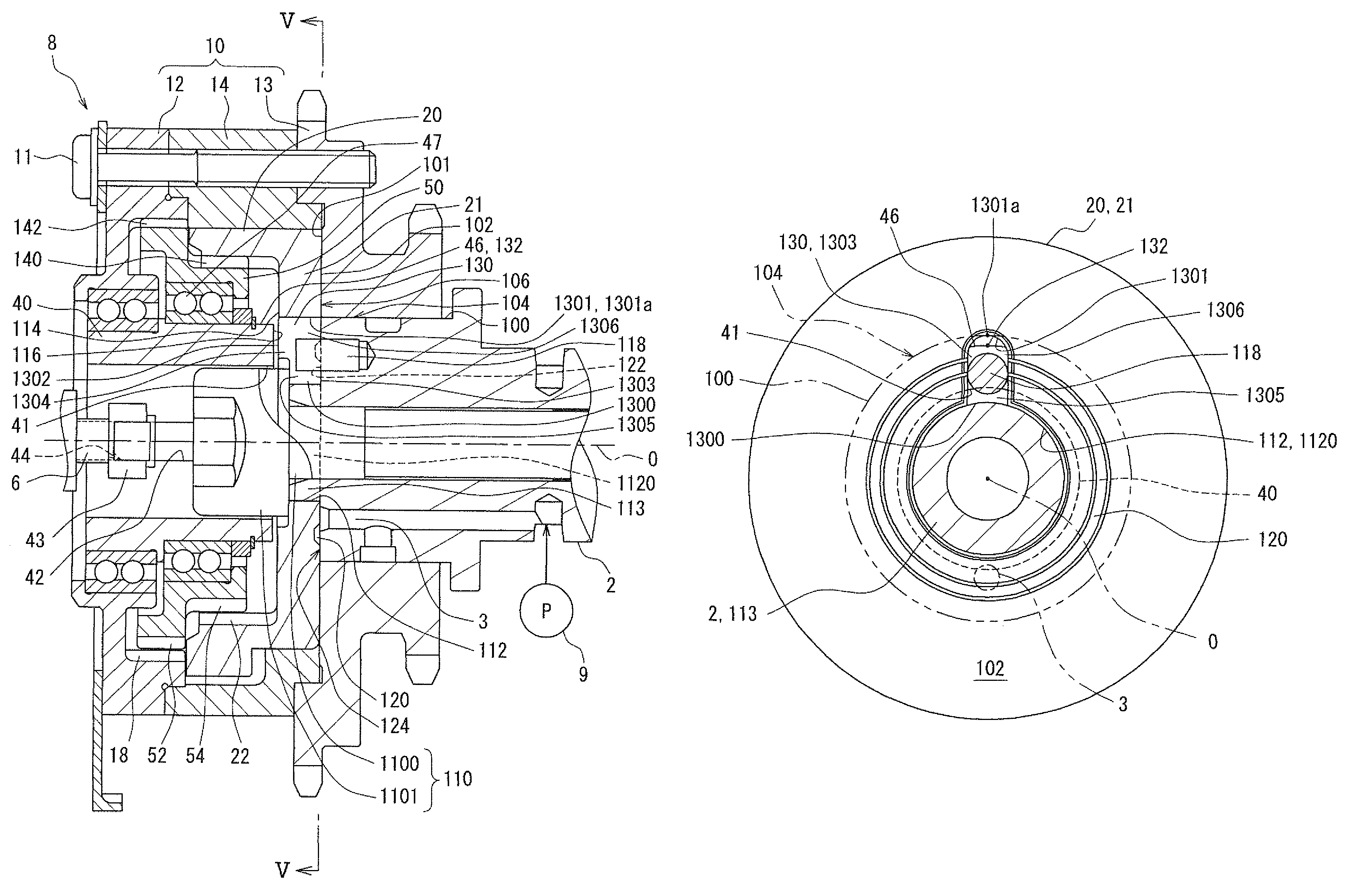
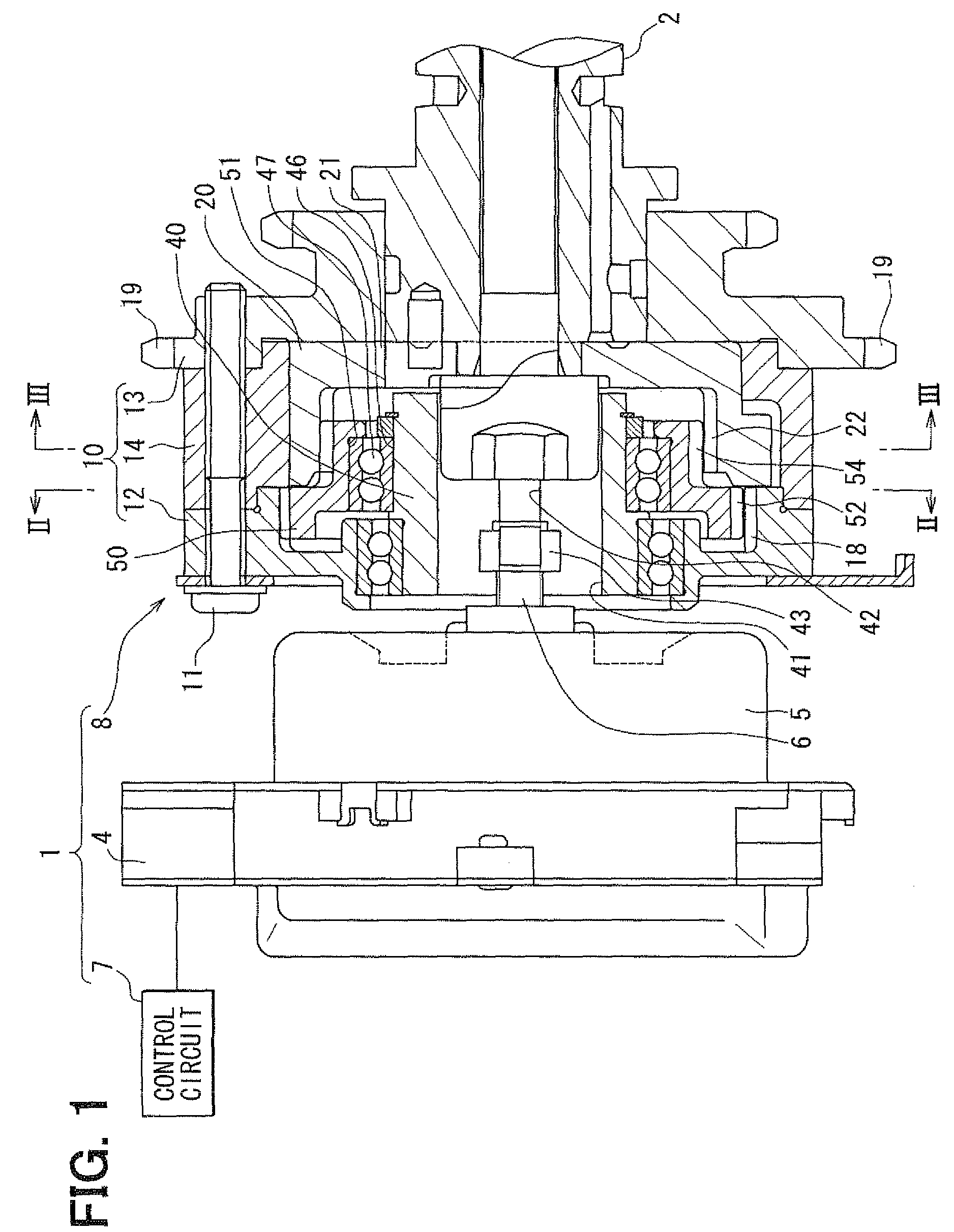
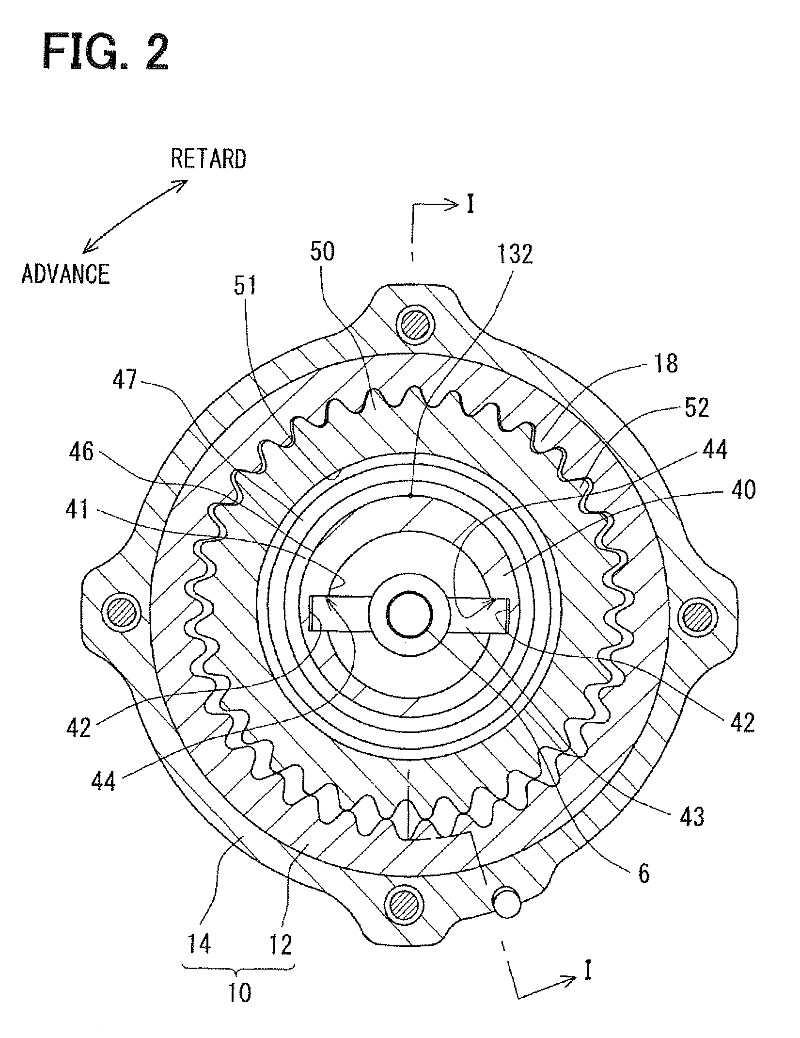
[0040]FIG. 1 shows a valve timing controller 1 according to a first embodiment of the present invention. The valve timing controller 1 is mounted on a vehicle, and more specifically, the valve timing controller 1 is mounted on a transmission system that transmits an engine torque from a crankshaft (not shown) to a camshaft 2 of an internal combustion engine. It should be noted that in the present embodiment the camshaft 2 opens and closes an intake valve (not shown) that serves as a “valve” of the internal combustion engine through transmission of the engine torque. The valve timing controller 1 adjusts a rotational phase between the crankshaft and the camshaft 2 to get a desired valve timing of the intake valve.

(Basic Configuration)

[0041]A basic configuration of the valve timing controller 1 of the first embodiment will be described below. The valve timing controller 1 includes an electric actuator 4, an energizing control circuit unit 7, and a phase adjusting mechanism 8.

[0042]The...

second embodiment

[0068]As shown in FIGS. 7 and 8, a second embodiment is a modification of the first embodiment. In the second and the successive embodiments, the same parts and components as those in the first embodiment are indicated with the same reference numerals and the same descriptions will not be reiterated. An outermost point 2301a of a bottom portion 2301 of the introducing port 230 is located apart from the maximum eccentric point 132 of the supporting outer surface 46 and the periphery surface 100 of the camshaft 2 with respect to the center line “O”. The introducing port 230 has a bottom portion 2301 which is radially outwardly located with respect to the periphery surface 100 of the camshaft 2. Thus, a second side-opening 2303 of the introducing port 230 on the driven-rotor-side-surface 102 radially extends across the supporting interface 104.

[0069]According to such a configuration, the lubricant in the space 1306 is easily introduced into the supporting interface 104 and the sliding ...

third embodiment

[0071]As shown in FIGS. 10 and 11, a third embodiment is a modification of the first embodiment. In the third embodiment, an outermost diameter of the annular groove 320 is larger than a diameter of the periphery surface 100 of the camshaft 2, which defines the supporting interface 104 in cooperation with the sprocket member 13. Also, the outermost radius of the annular groove 320 is larger than a distance between the outermost point 1301a and the center line “O”. Thus, a width of an opening 3200 of the annular groove 320 on the driven-rotor-side-surface 102 radially extends across the supporting interface 104. The stepped surface 122 of the camshaft 2 is in contact with the driven-rotor-side-surface 102 inside of the annular groove 320.

[0072]According to such a configuration, the annular groove 320 crossing the supporting interface 104 directly introduces the lubricant to the supporting interface 104 and the sliding interface 106, as shown in FIG. 12. Thus, the lubricating property...


PUM


Abstract

A valve timing controller is provided with a driving rotor rotating along with a crankshaft, a driven rotor rotating along with a camshaft, a planetary gear performing a planetary motion to adjust a rotational phase between the camshaft and the crankshaft, a motor shaft rotating for controlling the planetary motion, a cylindrical planetary carrier supporting the planetary gear and being connected with the control shaft so that the planetary gear performs the planetary motion, and a lubricating mechanism. The lubricating mechanism includes an introducing port which opens on a side surface of the second rotor axially confronting the planetary carrier. The introducing port extends across a supporting outer surface and a connecting inner surface. The lubricant is introduced into an interior of the first rotor through the introducing port.

Description

CROSS-REFERENCE TO RELATED APPLICATION[0001]This application is based on Japanese Patent Application No. 2009-11314 filed on Jan. 21, 2009, the disclosure of which is incorporated herein by reference.FIELD OF THE INVENTION[0002]The present invention relates to a valve timing controller which adjusts valve timing of a valve that is opened / closed by a camshaft driven by a torque transmitted from a crankshaft of an internal combustion engine.BACKGROUND OF THE INVENTION[0003]A valve timing controller has two rotors which rotate in synchronization with a crankshaft and a camshaft respectively. One of two rotors is provided with a gear portion engaging with a planetary gear. The planetary gear performs a planetary motion, so that a relative rotational phase between the crankshaft and the camshaft is adjusted. This relative rotational phase is referred to as a rotational phase, hereinafter.[0004]JP-2007-71056A shows a valve timing controller which has a lubricant introducing port provided ...

Claims


Application Information

Patent Timeline
Patent Type & Authority Patents(United States)
IPC IPC(8): F01L1/34
CPCF01L1/352
Inventor KURISU, MASAOSUGIURA, TAEI
Owner DENSO CORP
Why Eureka
Try Eureka