
Sheet feeding apparatus

a technology of feeding apparatus and sheets, which is applied in the direction of transportation and packaging, thin material processing, and article separation, etc., can solve the problems of difficult application of techniques, and achieve the effect of stabilizing the feed performance of sheets

Active Publication Date: 2012-08-28
CANON KK
View PDF21 Cites 9 Cited by
  • Summary
  • Abstract
  • Description
  • Claims
  • Application Information

AI Technical Summary

Benefits of technology

[0011]Thus, the object of the invention is to provide a feeder capable of detecting the stacked amount of sheets without adding a dedicated sensor or the like, in the feeder which keeps constant the operating amount of a pressure plate and stabilizes the feed performance of sheets.
[0013]According to the invention, it is possible to change the load of the separating operation of separating a sheet on the pressure plate from the feeding unit according to the turning angle of the pressure plate, thereby measuring a difference in driving load according to the angle of the pressure plate during separating operation, i.e., the stacked amount of sheets, and calculating the rough stacked amount simply from the measurement result. Additionally, since it is possible to calculate the measurement of the driving load from the PWM duty of motor driving, there is also no necessity of newly providing dedicated measuring unit. For this reason, it is possible to detect the sheet residual amount with a simple construction while suppressing a cost increase caused by the addition of a sensor.

Problems solved by technology

Therefore, it is difficult to apply the technique disclosed in Japanese Patent Application Laid-Open No.

Method used


Image

  • Sheet feeding apparatus
  • Sheet feeding apparatus
  • Sheet feeding apparatus

Examples


Embodiment Construction

[0026]An embodiment of a sheet feeding apparatus of the invention will now be described in detail with reference to the accompanying drawings. Here, although an ink jet printer to which the sheet feeding apparatus of the invention is applied will be described as an example, it is also possible to apply the sheet feeding apparatus of the invention to apparatuses other than the ink jet printer.

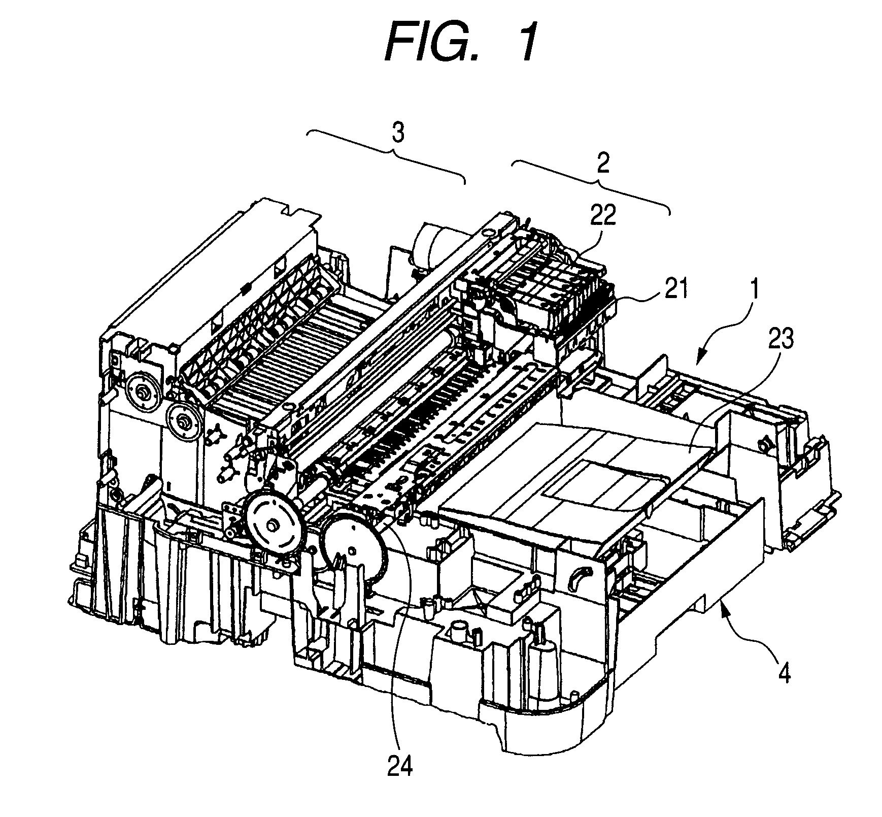
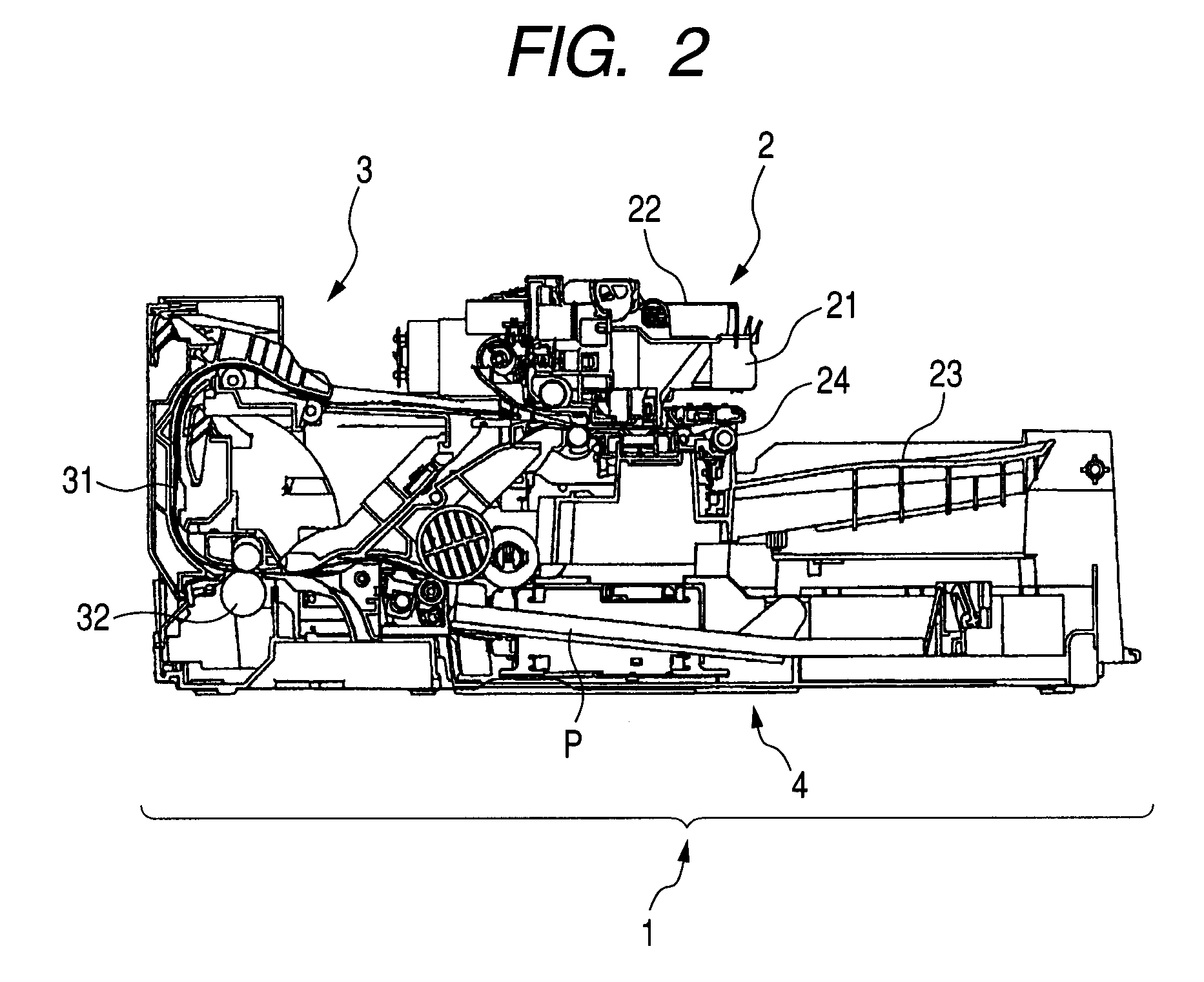
[0027]FIG. 1 is a perspective view illustrating the main internal configuration of an ink jet printer using the sheet feeding apparatus of the invention, and FIG. 2 is a sectional view illustrating main portions of the ink jet printer.

[0028]A main body 1 of the ink jet printer illustrated in FIGS. 1 and 2 includes a recording unit 2 which discharges ink drops to the surface of a sheet, thereby forming an image, and a sheet feeding apparatus 4 which separates and feeds recording paper sheets P which are the sheets stacked within the apparatus one by one. A recording paper P separated and fed from...


PUM


Abstract

A printer has a separating unit, such as a depressing cam and a depressing slider, which presses a middle plate against the biasing force of a spring and separates a sheet on the middle plate from a sheet feeding roller by a predetermined distance, a separation driving unit, such as a DC motor, which moves the separating unit, a measuring unit which measures the driving load applied to the separation driving unit when the separation driving unit drives the separating unit, and a load imparting unit, such as a brake plate, which imparts load to the middle plate, the separating unit, or the like. The brake plate or the like imparts load when a sheet is separated from the sheet feeding roller by the separating unit, and the brake plate or the like changes the load to be imparted, according to the turning angle of the middle plate.

Description

BACKGROUND OF THE INVENTION[0001]1. Field of the Invention[0002]The present invention relates to a sheet feeding apparatus which has sheets, such as a plurality of sheets of paper, stacked thereon, and supplies the sheets one by one to a main body of the device.[0003]2. Description of the Related Art[0004]Conventionally, in image forming apparatuses, such as a printer, a copying machine, and a facsimile, which perform separation and feeding for a plurality of stacked sheets and form an image on a sheet, there is a device which detects the amount of stacked sheets as described in Japanese Patent Application Laid-Open No. H03-079537. In this device, a message is issued or processing is changed depending on the amount of stacked sheets detected.[0005]Additionally, in a sheet feeding device which has sheets stacked on a pressure plate, moves the pressure plate up and down during sheet feeding, and makes a feed roller abut the upper surface of a paper, thereby performing feeding, there i...

Claims


Application Information

Patent Timeline
Patent Type & Authority Patents(United States)
IPC IPC(8): B65H1/26B65H1/10
CPCB65H1/12B65H3/0607B65H2405/1117B65H2511/212B65H2515/32B65H2515/704B65H2555/25B65H2801/06B65H2220/01B65H2220/11B65H2220/03B65H2220/02B65H2515/70
Inventor MORINAGA, KAZUYUKIKAWAZOE, KENJISHIMMACHI, MASAYAHAMANO, TETSUTOKISAWA, TOSHIAKI
Owner CANON KK
Learn More