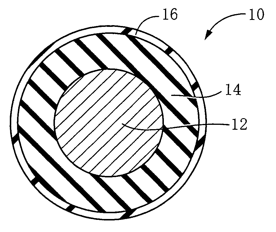
[0013]The present invention was made in view of the background art described above. It is therefore a first object of this invention to provide a semi-conductive roll including a coating layer formed by coating radially outwardly of a low-
hardness base layer, which semi-conductive roll exhibits a
wear resistance high enough to withstand a long period of use by improving the crosslinking density of the coating layer and which has a desired surface condition with high accuracy owing to ease of control of the thickness of the coating layer.
[0014]It is a second object of the invention to provide a semi-conductive roll which is produced with high economy and high efficiency, without suffering from defects on its surface due to agglomerates which arise from gelation of the coating liquid for forming the coating layer, even if the coating liquid is recycled.
[0015]In an attempt to achieve the objects indicated above, the inventors of the present invention made an extensive study and found that, in
sulfur crosslinking (
sulfur vulcanization) conventionally conducted for crosslinking (vulcanizing) the coating layer, the crosslinking density of the coating layer is deteriorated for the following reasons: The
sulfur as the crosslinking agent (vulcanizing agent) migrates or transfers to the low-hardness base layer by heating. Further, the inhibitory component of the base layer which inhibits the crosslinking of the coating layer transfers to the coating layer. The inventors further found the following: In the coating liquid which contains the sulfur crosslinking agent, the scorching progresses at
room temperature with a lapse of time, increasing the
viscosity of the coating liquid. If the
viscosity of the coating liquid is adjusted, by using a
solvent, to an intended value suitable for the coating method to be employed, the amount of the
solid component in the coating liquid is undesirably changed due to the addition of the solvent, making it difficult to control the thickness of the coating layer. The inventors found that the coating layer has a high crosslinking density if the coating layer is formed by resin crosslinking in which the rubber or
elastomer material is crosslinked by a resin material used as a crosslinking agent, in place of the conventional sulfur crosslinking. The semi-conductive roll whose coating layer has a high crosslinking density described above exhibits an improved resistance to wear. In addition, since the coating liquid which includes the resin crosslinking agent does not suffer from an increase in its viscosity due to the scorching of the rubber or
elastomer material included in the coating liquid, which scorching takes place at
room temperature, there is no need to adjust the viscosity by addition of the solvent, so that the amount of the
solid component contained in the coating liquid is kept constant, making it possible to easily control the thickness of the coating layer.

