
Circuit for controlling discharge amount of hydraulic pump

a hydraulic pump and discharge amount technology, applied in the direction of electrical appliances, mechanical appliances, couplings, etc., can solve the problems of reducing the decrease of the control interval of the inching control, so as to prevent a cavitation, reduce the inching control interval, and enhance the operation ability of equipment

Active Publication Date: 2005-12-20
VOLVO CONSTR EQUIP
View PDF8 Cites 10 Cited by
  • Summary
  • Abstract
  • Description
  • Claims
  • Application Information

AI Technical Summary

Benefits of technology

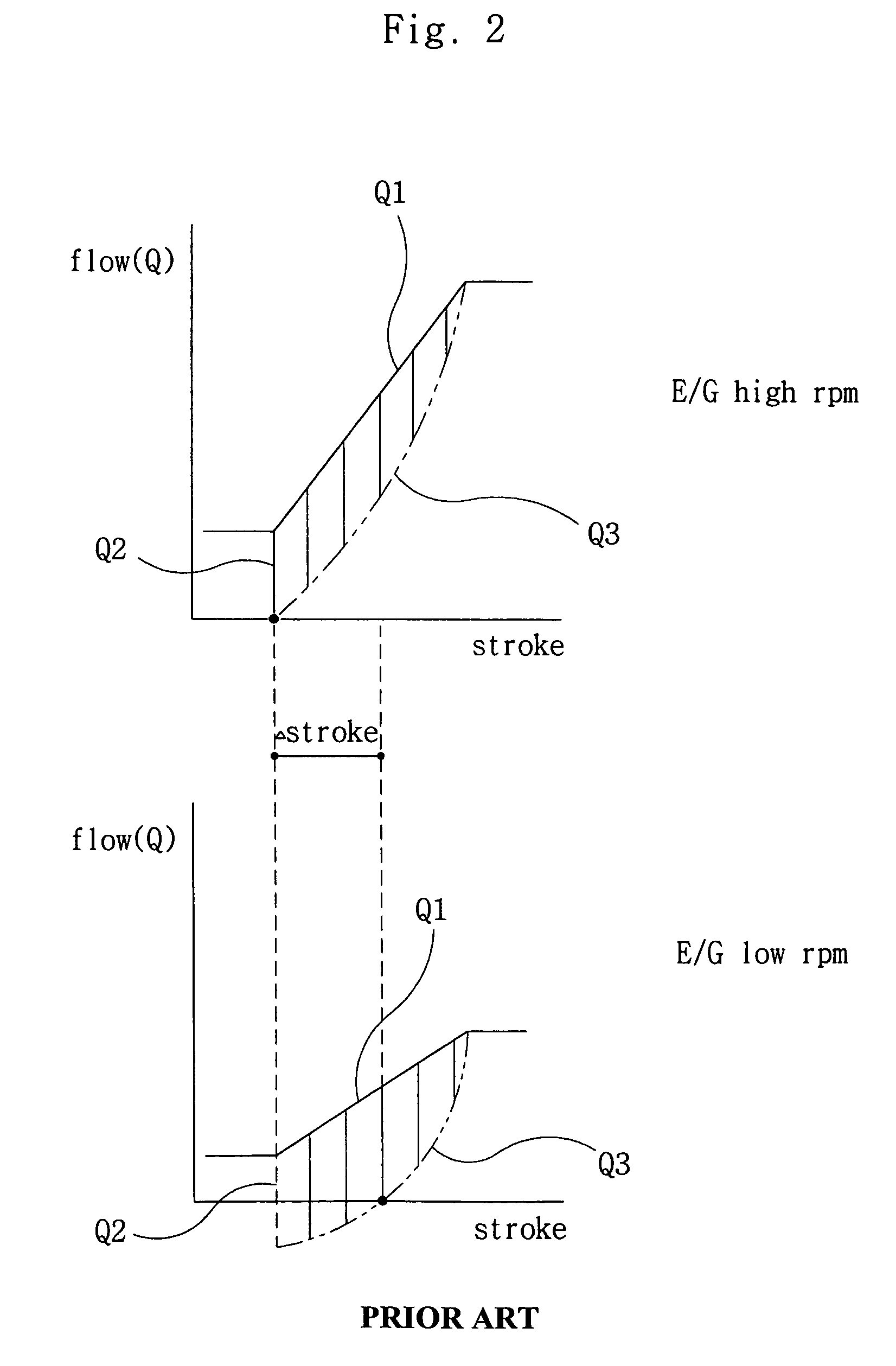
[0017]Accordingly, it is an object of the present invention to provide a circuit for controlling a discharge amount of a hydraulic pump, which is capable of constantly supplying a discharge amount of a hydraulic pump to a hydraulic cylinder irrespective of a load pressure of a hydraulic cylinder at a low speed rotation of an engine.
[0018]It is another object of the present invention to provide a circuit for controlling a discharge amount of a hydraulic pump, which is capable of preventing a cavitation due to a lack of discharge amount and enhancing an operation ability of equipment because an inching control interval is decreased.
[0019]It is further another object of the present invention to provide a circuit for controlling a discharge amount of a hydraulic pump, which is capable of supplying a constant discharge amount of hydraulic fluid to a hydraulic cylinder irrespective of a load pressure because it is possible to obtain the same effect as a load sensing in a negative or positive system.

Problems solved by technology

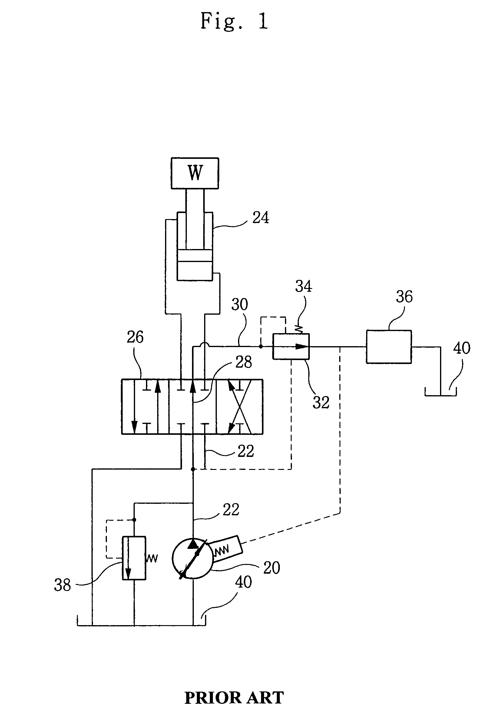
In addition, since the spool strokes of the switching valve are switched more in order to obtain a discharge amount by the lacking discharge amount, an inching control interval is decreased, and an operation ability of equipment is decreased.

Method used


Image

  • Circuit for controlling discharge amount of hydraulic pump
  • Circuit for controlling discharge amount of hydraulic pump
  • Circuit for controlling discharge amount of hydraulic pump

Examples


Embodiment Construction

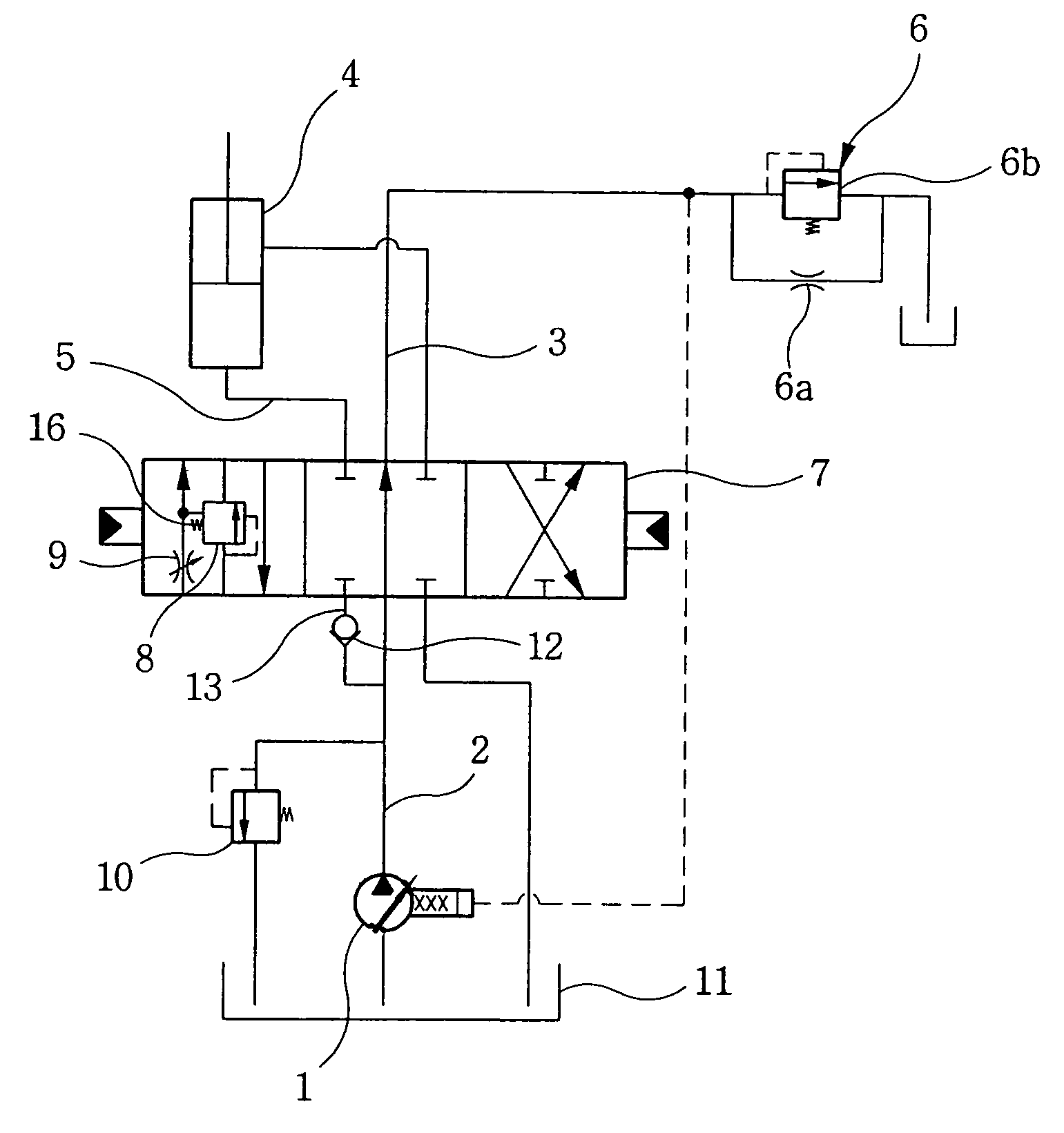
[0033]As shown in FIGS. 3 and 6, there are provided a variable displacement hydraulic pump 1 connected with an engine, an actuator 4 (referred to a hydraulic cylinder, etc.) which is connected with the hydraulic pump 11 through a supply flow path 2, a center bypass type directional switching valve 7 which is installed in a flow path between the hydraulic pump 1 and the actuator 4 and is adapted to control a start, stop and direction switching operation of the actuator 4 during a switching operation, and a pilot signal generation unit 6 which is installed in a down stream of the center bypass path 3 of the directional switching valve 7 and is adapted to control a discharge amount Q1 of the hydraulic pump 1. The above construction is actually the same as the construction of FIG. 1. Therefore, the detailed descriptions of the construction and operation will be omitted.

[0034]As shown in FIG. 3, a circuit for controlling a discharge amount of a hydraulic pump according to an embodiment o...


PUM


Abstract

A circuit for controlling a discharge amount of a hydraulic pump to an actuator irrespective of a load pressure of the actuator even when an engine operates at a low speed has a variable displacement hydraulic pump connected with the engine; an actuator connected with the hydraulic pump; a center-bypass directional switching valve in a flow path between the hydraulic pump and the actuator for controlling start, stop and directional switching of the actuator during a switching operation; a pilot signal generating means in a down stream side of the center bypass for controlling the discharge amount of the hydraulic pump; and a discharge amount adjusting valve in a supply path of the actuator of the directional switching valve for controlling a discharge amount of hydraulic fluid to the actuator.

Description

BACKGROUND OF THE INVENTION[0001]1. Field of the Invention[0002]The present invention relates to a circuit for controlling a discharge amount of a hydraulic pump which is capable of obtaining and supplying a constant flow amount of hydraulic fluid in a hydraulic pump supplied to an actuator such as a hydraulic cylinder which is adapted to drive a work apparatus for a construction heavy equipment, irrespective of a load pressure of a hydraulic cylinder, and in particular to a circuit for controlling a discharge amount of a hydraulic pump which is capable of constantly supplying a discharge amount of a hydraulic pump to a hydraulic cylinder irrespective of a load pressure of a hydraulic cylinder even when an engine operates at a low speed.[0003]Among the terminologies used herein, the terminology “Negative system” represents a method for decreasing a discharge amount of a variable displacement hydraulic pump in the case that pilot pressure discharged from an upper stream of a pilot si...

Claims


Application Information

Patent Timeline
Patent Type & Authority Patents(United States)
IPC IPC(8): H05K9/00E02F9/22F15B9/08F15B11/00F15B11/02F15B11/05F15B11/16
CPCE02F9/2221F15B11/055F15B11/167F15B2211/20553F15B2211/255F15B2211/3116F15B2211/329F15B2211/351F15B2211/355F15B2211/40507F15B2211/41554F15B2211/45F15B2211/50518F15B2211/5156F15B2211/575F15B9/08
Inventor KIM, JIN WOOK
Owner VOLVO CONSTR EQUIP
Learn More