
Removable radiation sensor for dental imaging systems

a radiation sensor and dental imaging technology, applied in the field of dental radiation imaging systems, can solve the problems of many extraoral radiation devices, transferable sensors, and inability to have cephalometric capabilities, and achieve the effects of low resistance and capacitance connection, high current capability, and convenient movemen

Active Publication Date: 2012-08-28
MIDMARK
View PDF16 Cites 8 Cited by
  • Summary
  • Abstract
  • Description
  • Claims
  • Application Information

AI Technical Summary

Benefits of technology

The solution provides a cost-effective, reliable, and durable sensor system that can withstand 10,000 insertions or more, reducing the overall cost of ownership and enabling easy maintenance and diagnostic functionalities without compromising image quality.

Problems solved by technology

Many extraoral radiation devices, such as the Planmeca ProOne™, Kodak 8000, Gendex Orthoralix™ 8500 DDE, and the Sirona Orthophos™ 3 DS, do not have cephalometric capabilities.
Others, such as the Kodak 9000C, provide cephalometric capabilities, but do not have a transferable sensor.
The radiation sensors for panoramic and cephalometric imaging systems are very costly components, and thus greatly increase the overall cost of the systems.
Those systems, however, employ connection systems that are complicated, less reliable, and / or expensive.
Further, most of the commonly used connectors in those systems have limited durability, on the order of 500 insertions.
This durability sometimes is not enough for the long term usage of certain extraoral X-Ray devices, especially because of the usual long lifespan of more than ten years.
That choice, however, adds cost to the sensor, and limits the sensor connector only to the essential data signals and power lines.

Method used


Image

  • Removable radiation sensor for dental imaging systems
  • Removable radiation sensor for dental imaging systems
  • Removable radiation sensor for dental imaging systems

Examples


Embodiment Construction

[0025]This application is being filed at the same time as a patent application on a patient positioning system for a panoramic dental radiation imaging system, and a patent application on a motion system for a dental imaging system, and a design patent application on a dental imaging system, all filed on the same day as this application and assigned to the same assignee. The disclosure of each of those other patent applications is incorporated herein by reference.

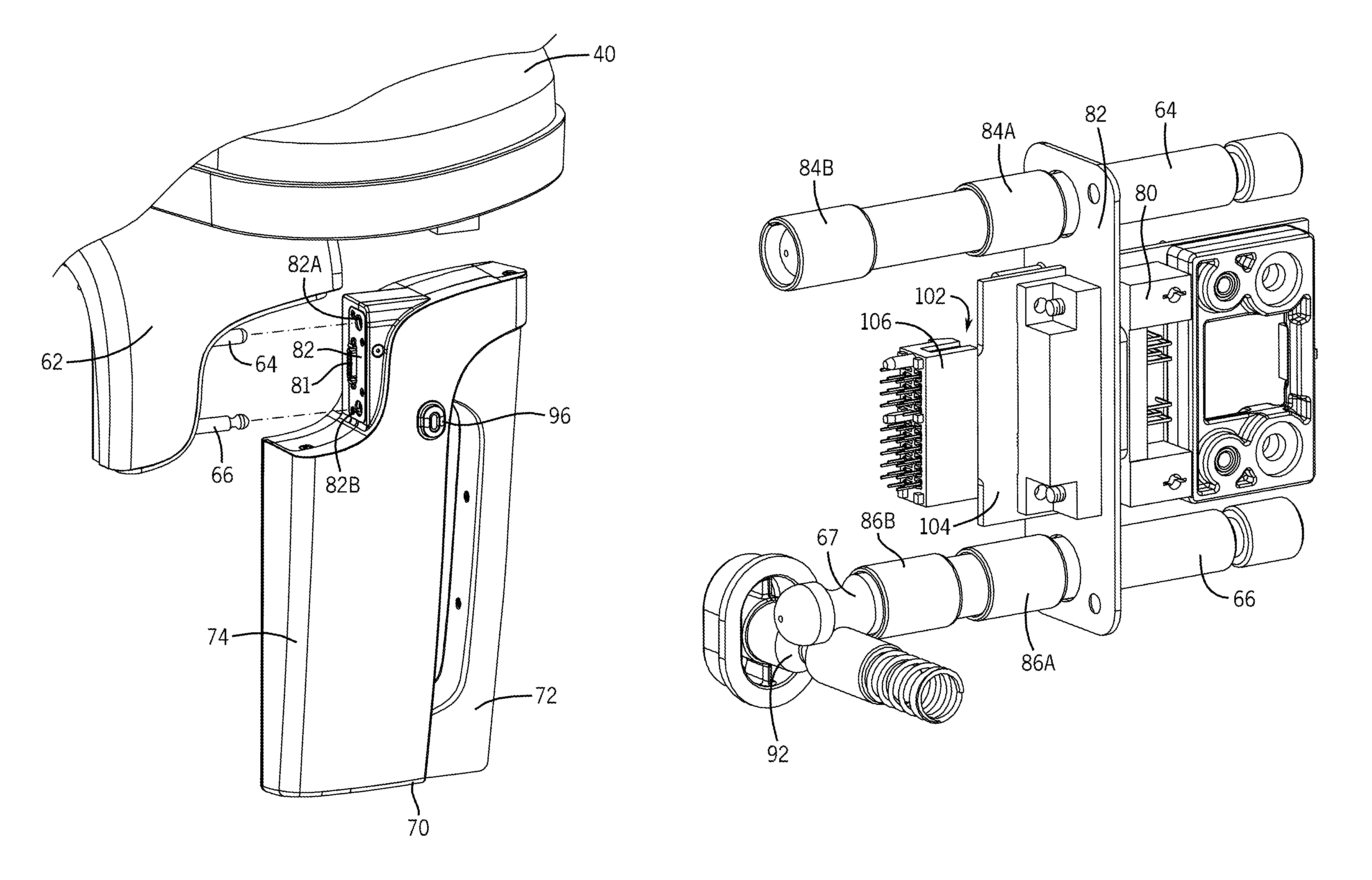
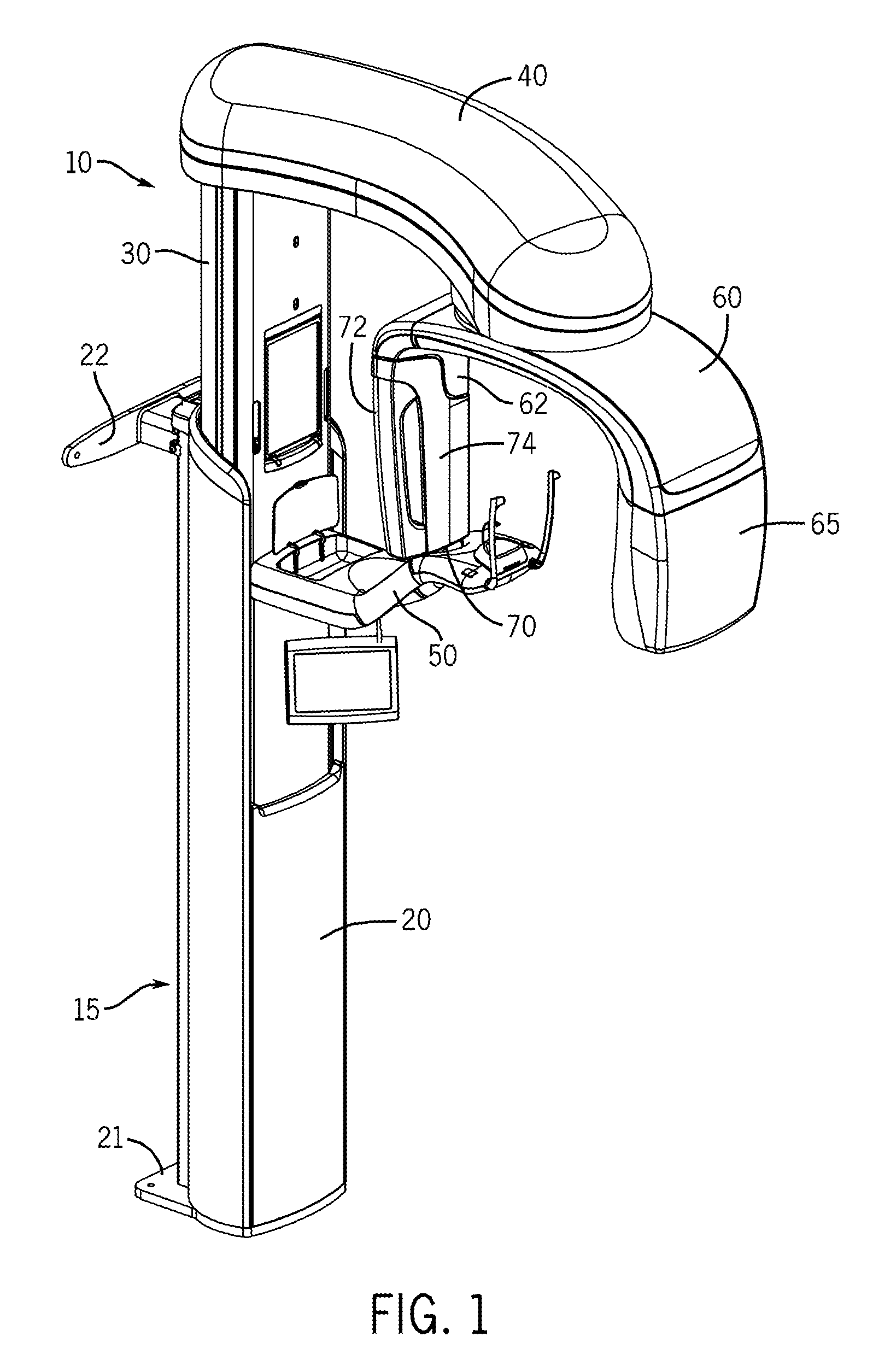
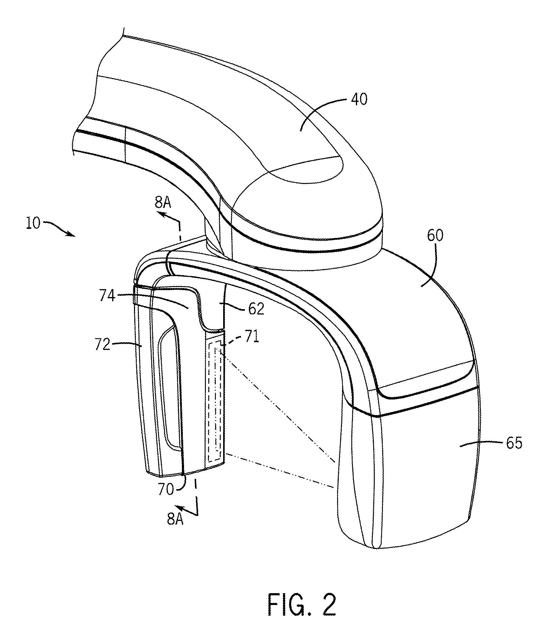
[0026]One embodiment of a panoramic dental radiation imaging system 10 with a removable radiation sensor body 70, having a radiation sensor unit 71 inside, is shown in FIG. 1. While the invention may be susceptible to embodiment in different forms, there is shown in the drawings, and herein will be described in detail, certain illustrative embodiments with the understanding that the present disclosure is to be considered an exemplification of the principles of the invention, and is not intended to limit the invention to tho...


PUM


Abstract

A removable radiation sensor for connecting to a panoramic dental radiation imaging system. The sensor includes a radiation sensor unit mounted in a housing. Connector bearings are positioned within the housing so as to engage with a pair of connector pins provided as part of the upright support of the imaging system. A lock pin within the housing is selectively slidable between Locked and Unlocked, and biased toward Locked. The lock includes a locking pin with a groove, and when the groove is aligned with the respective connector pin, the lock is unlocked, and that connector pin is slidable axially within the bearings. When the groove is not aligned with the connector pin, the lock is locked, the locking pin engaging with a groove formed for that purpose in the connector pin. The sensor has a field-replaceable electrical connector, to reduce maintenance cost.

Description

BACKGROUND OF THE INVENTION[0001]This invention relates to dental radiation imaging systems, and in particular to systems having a removable radiation detector so as to permit varied uses of the detector.[0002]Panoramic and cephalometric dental radiation imaging is used to obtain images of a patient's teeth and jaws. Radiation imaging is essential in providing accurate information in the diagnostic process. Imaging techniques, such as bitewing (interproximal), edentulous (toothless), full mouth series, occlusal, periapical, panoramic techniques, and others, provide information in discovering tooth decay, broken fillings, tumors, occlusal trauma, and other effects that would otherwise be unseen by the eye, whether located inside the teeth, between the teeth, or below the gum line, within the gum tissue. In general, the radiological examinations in dentistry may be classified as intraoral and extraoral, determined by where the radiation sensor is placed with respect to the mouth.[0003...

Claims


Application Information

Patent Timeline
Patent Type & Authority Patents(United States)
IPC IPC(8): A61B6/14H05G1/02H05G1/64H05G1/08A61B6/51
CPCA61B6/14A61B6/4411A61B6/4441A61B6/51
Inventor CEKOV, LYUBOMIR L.KANTOR, ARKADYWALKER, DONALDKREMA, ALAN P.
Owner MIDMARK
Learn More