
Three-dimensional digital magnifier operation supporting system

a technology of operation support system and digital magnifier, which is applied in the field of medical navigation operation support system, can solve the problem of time limit of methods, and achieve the effect of improving operation efficiency and implementing high-precision operations

Active Publication Date: 2012-08-28
ATSUSHI TAKAHASHI
View PDF6 Cites 61 Cited by
  • Summary
  • Abstract
  • Description
  • Claims
  • Application Information

AI Technical Summary

Benefits of technology

"The present invention provides a system for using a three-dimensional digital magnifier to provide visual support for invisible areas during medical operations or precise manipulation. The system takes pictures of the subject and measures its position in real-time using a stereo arrangement camera and a stereo method. The system also uses invisible light sources, such as infrared ray, which do not impact the operator's eyesight. The system can display and track the position of the patient's body and the operation instruments, allowing for better tracking and positioning during the operation. The system can also update the images in real-time, providing a real-time view of the patient's body and the changes caused by the operation. Overall, the system improves the precision and speed of positioning and tracking during medical operations."

Problems solved by technology

Therefore, in order to improve position precision and to correct displacement of the sensing marker, MRI shooting is performing during operation, and registration and tracking are performed while updating the images, however, from a real-time viewpoint, because the MRI shooting takes time, this method has time limit, and this is not a favorite situation for a surgery operation.

Method used


Image

  • Three-dimensional digital magnifier operation supporting system
  • Three-dimensional digital magnifier operation supporting system
  • Three-dimensional digital magnifier operation supporting system

Examples


Embodiment Construction

Best Modes for Implementing the Invention

[0115]Here, description of the embodiments of the present invention is provided referring to the accompanied drawings.

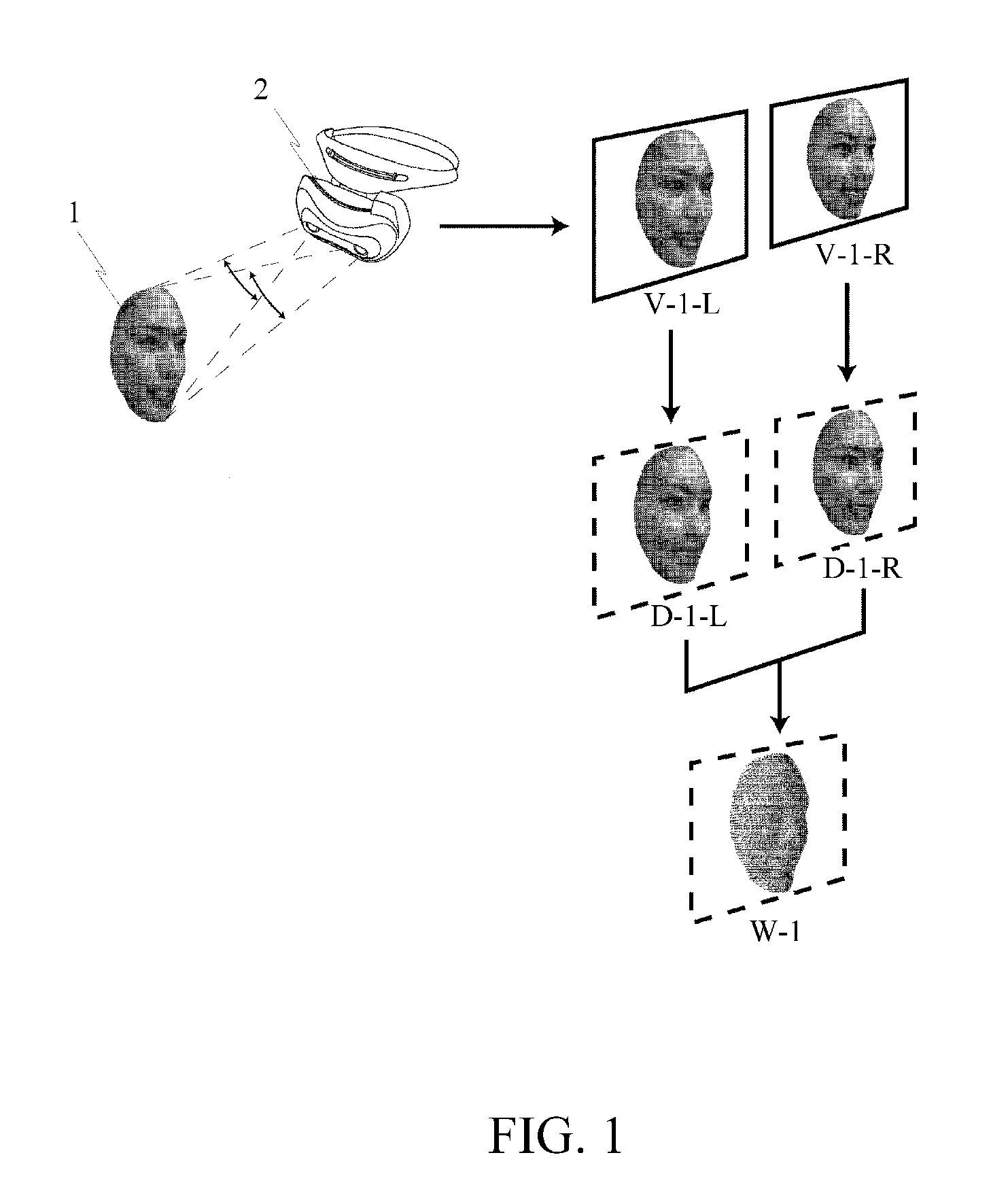
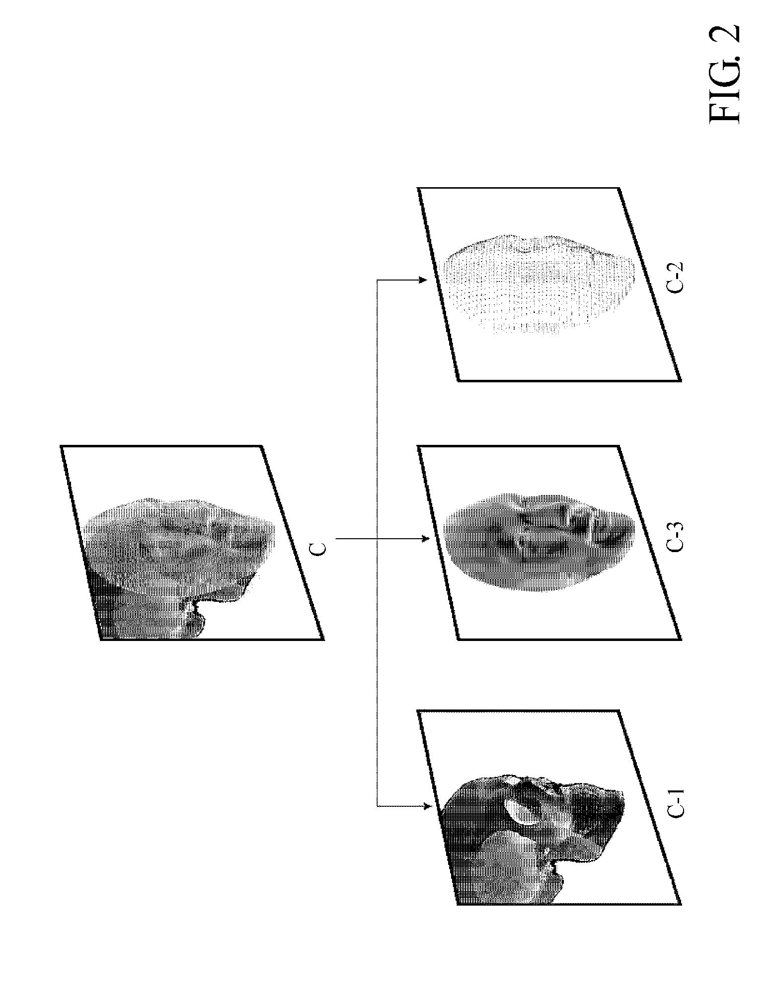
[0116]FIGS. 1˜10 represent exemplary elements and embodiments of the present invention. Frames in the drawings represent monitor image of a digital magnifier, recognized image of a monitor or an image on PC monitor. The thing showing three-dimensional representation by the right and left monitors is accompanied with the digital magnifier monitor. In addition, the parts which are labeled with the same symbols represent the same thing.

[0117]The working principal of the three-dimensional digital magnifier constituting the present invention is, when images projected on retina by human eyes are identified by the brain, a living system identifying distances using angle of parallax of left and right eyes is manipulated, a three-dimensionally identified condition is reproduced by vision on an image display device positioned in front o...


PUM


Abstract

The simulation regarding the state change of the subject in a real space provides a system which represents impacts to three-dimensional computer graphics caused by changes of state of three-dimensional computer graphics composed and fixed to subject, and state of image taking space by simulation, surface polygon model and similar surface polygon model 1 is selected, according to shape pattern, from surface polygon model 2 measures, in a three-dimensional way, subject image existing in the same space, a tracking process is performed on the computer graphics, following to the relative position change of the position changes of the subject and the camera caused in real three-dimensional space, subjects in the visual field of the camera and virtual three-dimensional computer graphics image is unified and displayed by displaying computer graphics image having the same relative position change on the image.

Description

BACKGROUND OF THE INVENTION[0001]1. Field of the Invention[0002]The present invention relates to a medical navigation operation support system for showing positional relation between a patient body and operational instruments during an operation, in order to improve safety and reliability when approaching invisible areas in a least invasive surgical operation. More specifically, the present invention relates to a three-dimensional digital magnifier operation support system, which displays invisible parts or three-dimensional computer graphics of outward appearance of a solid object (patient body and operational instruments) on top of three-dimensional image of the solid object recognized by a three-dimensional digital magnifier, in order to unify the substantial object image and the virtual three-dimensional computer graphics for recognizing it as a whole in a three-dimensional way.[0003]2. Description of the Related Art[0004]Conventionally, when approaching invisible parts in a sur...

Claims


Application Information

Patent Timeline
Patent Type & Authority Patents(United States)
IPC IPC(8): H04N13/00G06K9/00A61B6/51
CPCA61B19/52A61C1/084A61B6/506A61B2019/5291A61B90/36G06T2200/08G06T2207/10012G06T2207/10081G06T2207/10088G06T2207/30036G06T19/00A61B2090/371A61B2090/365G06T7/33A61C19/04A61B6/51A61B17/24
Inventor ATSUSHI, TAKAHASHI
Owner ATSUSHI TAKAHASHI
Learn More