Bandwidth control apparatus

a control apparatus and bandwidth technology, applied in the field of bandwidth control apparatus and communication control semiconductor, can solve the problems of inflexible equipment configuration, difficult to identify from the amount of packets stored in the buffer whether or not the user is the user, and the tendency of heavy users to occupy the line bandwidth, etc., to achieve the effect of correcting the bias in the communication bandwidth

Active Publication Date: 2012-08-28
ALAXALA NETWORKS
View PDF15 Cites 7 Cited by
  • Summary
  • Abstract
  • Description
  • Claims
  • Application Information

AI Technical Summary

Benefits of technology

[0011]By the bandwidth control technique as in JP-A-2003-198611, it becomes possible to correct the bias in the communication bandwidth between users at the time of network congestion. However, since the bandwidth control is performed without differentiating between the heavy user who gives the excessive load to the network and the light user, when viewed in a long-term span, it is impossible to correct the tendency that the heavy user is liable to occupy the line bandwidth. For the ISP in which traffic increase is a problem, it is necessary to provide a bandwidth control technique which can correct the tendency that the heavy user occupies the line bandwidth.

Problems solved by technology

However, since the bandwidth control is performed without differentiating between the heavy user who gives the excessive load to the network and the light user, when viewed in a long-term span, it is impossible to correct the tendency that the heavy user is liable to occupy the line bandwidth.
However, it is difficult to identify from the amount of packets stored in the buffer whether or not the user is the heavy user.
Besides, since the control packet is exchanged between the communication equipments, the load is exerted on the network, and the input side node is required to be provided with a bandwidth suppression function based on the information of the control packet, and there is a problem that the equipment configuration lacks flexibility.
However, even if there is an upper limit of the communication amount, there is a heavy user who attempts to perform communication to the utmost within the range not reaching the upper limit value, and the fundamental solution of the problem is not achieved.
Besides, when the upper limit of the communication amount is provided, the free use of the network is prevented, and there is a case where the attraction of the communication service is spoiled.
Thus, the analysis process is very complicated and is liable to become the bottle neck in the performance.
Besides, the performance deterioration of the network is caused, there is a high possibility that a delay due to the process waiting until the traffic analysis is completed occurs, and there is a case where an influence is exerted on the reduction of the effective speed of Transmission Control Protocol (TCP) communication and easiness of conversation in bidirectional real-time communication such as telephone.
Besides, in order to install the apparatus dedicated to the traffic analysis in the whole country, a vast increase in cost can not be avoided, and there is a case where the profit of each ISP is compressed.

Method used


Image

  • Bandwidth control apparatus
  • Bandwidth control apparatus
  • Bandwidth control apparatus

Examples


first embodiment

1. First Embodiment

(Structure of the Apparatus)

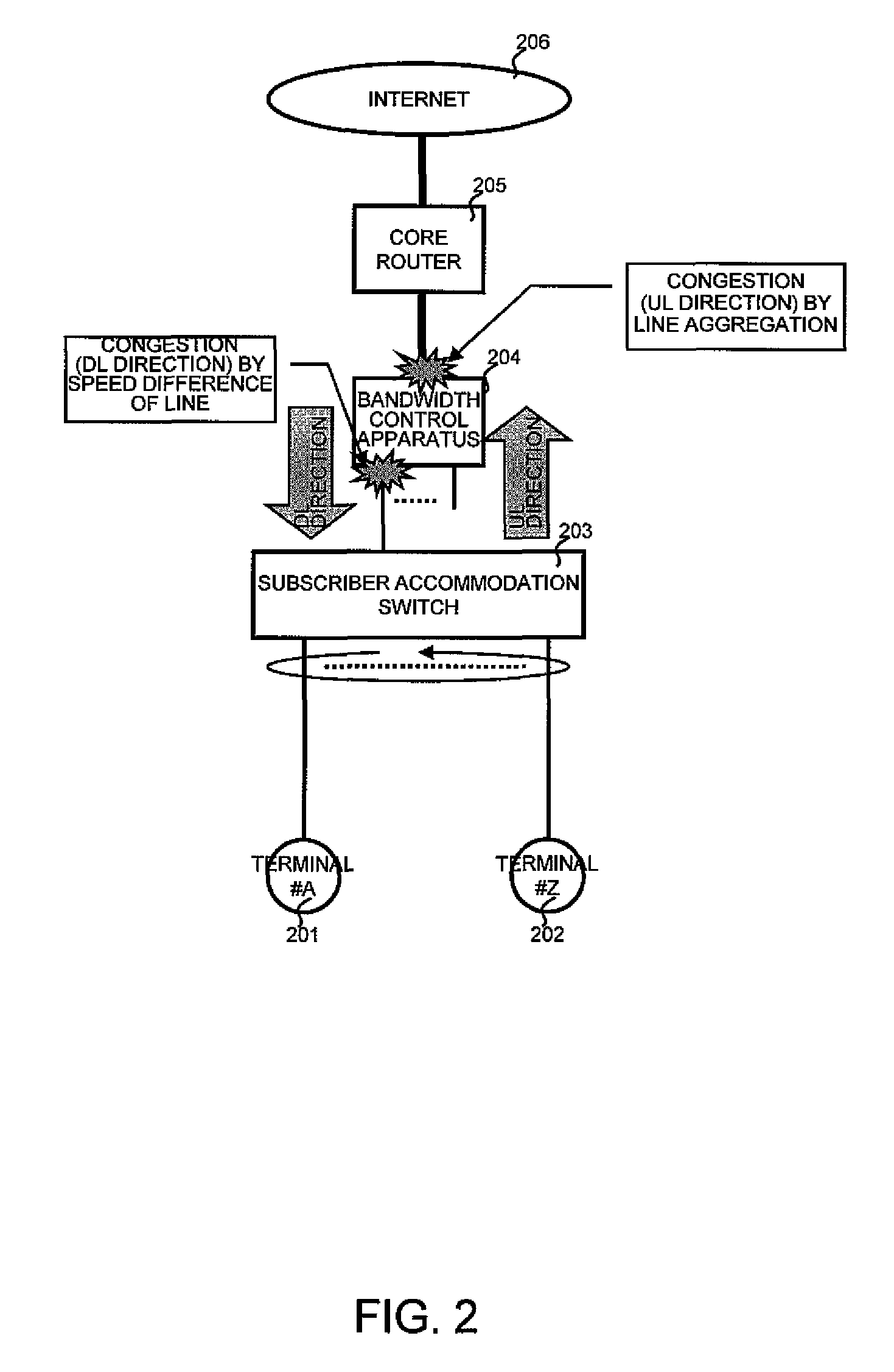
[0079]FIG. 2 is a structural view of a user accommodation network.

[0080]FIG. 2 shows a conceptual image of the user reception network such as Fiber To The Home (FTTH) or Asymmetric Digital Subscriber Line (ADSL), and shows the physical structure of the network which is an application area of a bandwidth control apparatus.

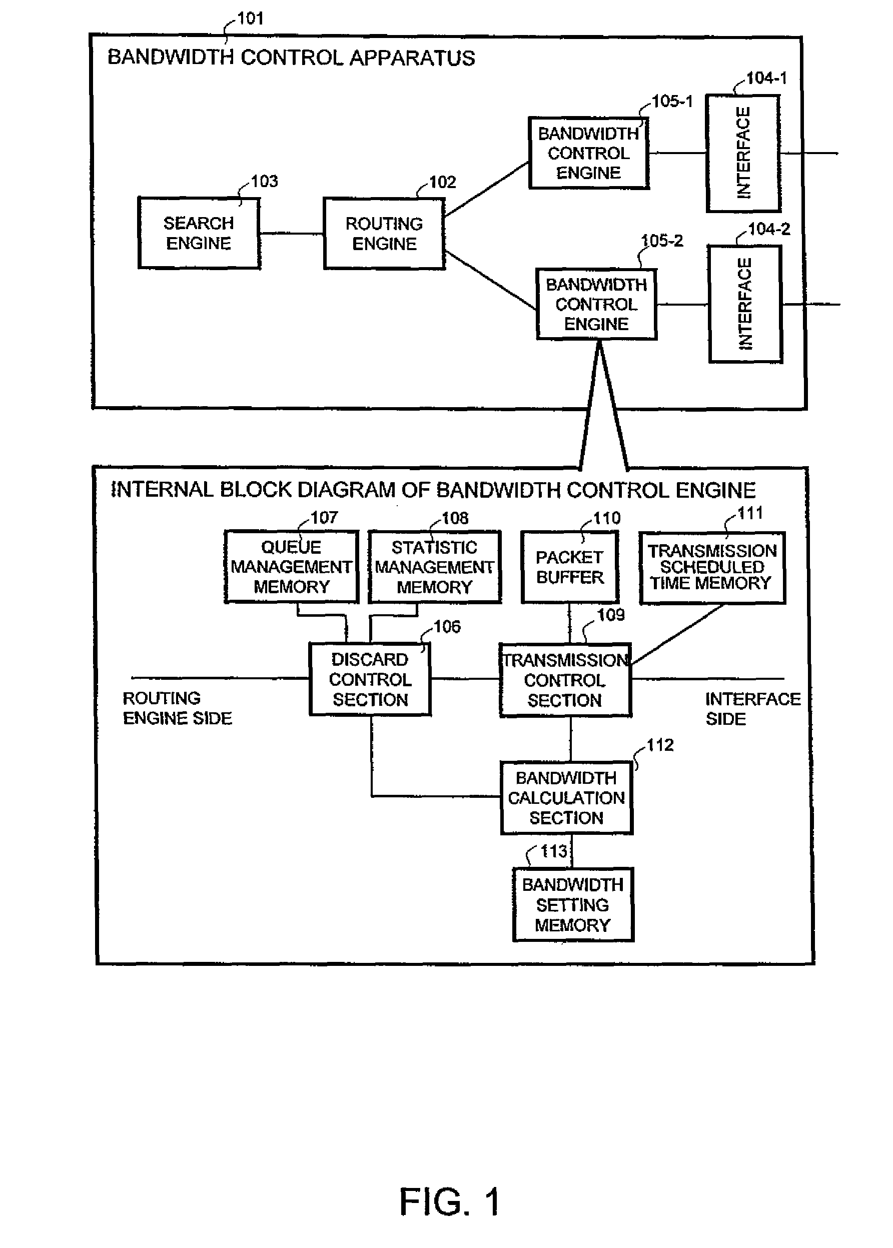
[0081]In the user reception network of FIG. 2, a bandwidth control apparatus 204 is disposed between, for example, a core router 205 and a subscriber accommodation switch 203. Incidentally, a bandwidth control function may be incorporated in the core router 205 or the subscriber accommodation switch 203.

[0082]The bandwidth control apparatus 204 is placed between, for example, the core router 205 at the higher line side and the subscriber accommodation switch 203 at the lower line side, and the network structure is such that communication between a terminal 201, 202 and the Internet 206 is performed via the bandwidth con...

second embodiment

2. Second Embodiment

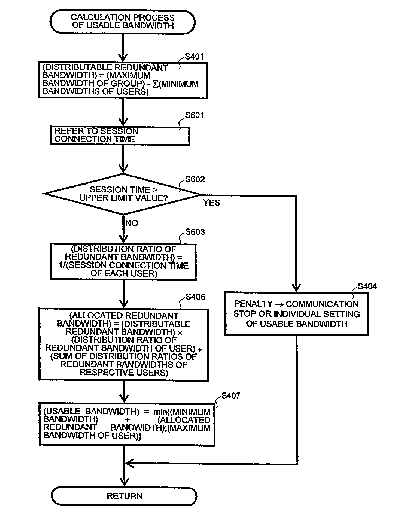
[0144]In a second embodiment, there is provided a bandwidth control function by a usable bandwidth calculated based on a session connection time of each user. Incidentally, a structure of a bandwidth control apparatus 101, a structure of each memory, and an operation of bandwidth control are the same as those of the first embodiment. The calculation process (FIG. 4) of the usable bandwidth in the first embodiment is replaced by a process described below.

[0145]The session connection time is an elapsed time when each user continuously performs communication. In the P2P communication, communication is performed via adjacent clients, and as a feature of a client (hereinafter referred to as a super node) to exert a bad influence on the network, the client has a high line speed, is adjacent to many clients, holds highly demanded information resources, receives download requests from other clients successively, and has a tendency that the communication is performed cont...


PUM


Abstract

A bandwidth calculation section calculates a usable bandwidth from a communication amount of each user or a session connection time stored in a statistic management memory and minimum bandwidth information and maximum bandwidth information recorded in a bandwidth setting memory. The bandwidth calculation section allocates a large usable bandwidth to a user with a small communication amount or a short session connection time. A transmission control section performs transmission scheduling of packet information stored in a packet buffer based on a transmission scheduled time calculated from the usable bandwidth stored in a transmission scheduled time memory.

Description

CLAIM OF PRIORITY[0001]The present application claims priority from Japanese patent application JP 2009-015707 filed on Jan. 27, 2009, the contents of which are hereby incorporated by reference into this application.BACKGROUND OF THE INVENTION[0002]1. Field of the Invention[0003]The present invention relates to a bandwidth control apparatus and a communication control semiconductor, and particularly to a bandwidth control apparatus and a communication control semiconductor in which in a communication field such as an IP network, a usable bandwidth is calculated based on a previously set minimum bandwidth and maximum bandwidth, and information of a communication amount or session connection time, and bandwidth control can be performed.[0004]2. Description of the Related Art[0005]Since the access control of Ethernet technique (Ethernet is a registered trademark) used in an Internet network or in-company LAN is controlled by the Carrier Sense Multiple Access / Collision Detection (CSMA / C...

Claims


Application Information

Patent Timeline
Patent Type & Authority Patents(United States)
IPC IPC(8): H04L12/26H04L47/76
CPCH04L47/10H04L47/20H04L47/2475H04L47/28H04L47/32
Inventor HINOSUGI, HIDEKIANZAI, ATSUSHIKUMAGAI, TAKESHI
Owner ALAXALA NETWORKS
Why Eureka
Try Eureka