Method and apparatus for increasing coherent integration length while receiving a positioning signal

a technology of coherent integration and positioning signal, which is applied in the direction of pulse technique, amplitude demodulation, instruments, etc., can solve the problems of reducing the power of the receiver, reducing the coherent integration length, and difficult to receive positioning signals from gps satellites. achieve the effect of increasing the coherent integration length

Active Publication Date: 2012-08-28
QUALCOMM INC
View PDF18 Cites 5 Cited by
  • Summary
  • Abstract
  • Description
  • Claims
  • Application Information

AI Technical Summary

Benefits of technology

[0010]A method and apparatus are described herein for increasing the coherent integration length for receiving and processing one or more positioning signals transmitted from a plurality of transmitters at predetermined frequencies, which are used in determining a location of a receiver. Each positioning signal includes a periodically-repeating sequence that uniquely identifies the transmitter that sent the signal.
[0011]In order to compensate for frequency drifts that may occur in the positioning signal after observation and processing in a receiver, one or more hypotheses are made as to the frequency drift, which, in one embodiment, are then combined with observed data and processed. This allows a longer coherent integration length, which can significantly reduce processing time and / or provide a more accurate result. Particularly, by applying frequency drift hypotheses in the signal processing, the length of coherent integration can be increased at the expense of reducing the length, of incoherent integration while keeping the total integration length the same, the net effect of which is an increase in signal detection sensitivity.
[0015]Advantageously, the disclosed method allows a longer coherent integration period, thereby using a longer data block than conventional receiver methods. For example, the data block may have a size within a range of one hundred to five hundred repetitions of the reference signals, or within a range of one hundred milliseconds to one second. However, it may still be advantageous to utilize the disclosed method with shorter coherent integration periods, for example ten to one-hundred milliseconds.

Problems solved by technology

However, because the GPS code and phase delay is initially unknown, an approach is typically employed in which a first GPS code is hypothesized and a number of phase assumptions are then tested sequentially until the GPS signal has been either identified or determined not to be present.
Receiving positioning signals from GPS satellites can be difficult due to a number of factors.
By the time the GPS signals travel from earth orbit to a receiver, their initially low power has been greatly reduced, rendering the signal extremely weak at the receiver.
Another problem relates to frequency errors that can affect one or more of the positioning signals.
In the receiver, the oscillators and other electronic devices that receive and process the signal can introduce errors such as slight shifts in frequency, which can complicate reception.
If the frequency shift is constant, a Fourier transform (e.g., an FFT) approach can be used; however, further complications result when this frequency shift varies over time; i.e., when the frequency shift is not constant over the observation time (the data block).
In order to address the problem of time-varying frequency errors, the length of the data block for coherent processing (coherence length) is usually limited to a fraction of a second (e.g., 20 milliseconds); otherwise, the frequency errors could greatly degrade the system sensitivity.

Method used


Image

  • Method and apparatus for increasing coherent integration length while receiving a positioning signal
  • Method and apparatus for increasing coherent integration length while receiving a positioning signal
  • Method and apparatus for increasing coherent integration length while receiving a positioning signal

Examples


Embodiment Construction

[0026]This invention is described in the following description with reference to the Figures, in which like numbers represent the same or similar elements.

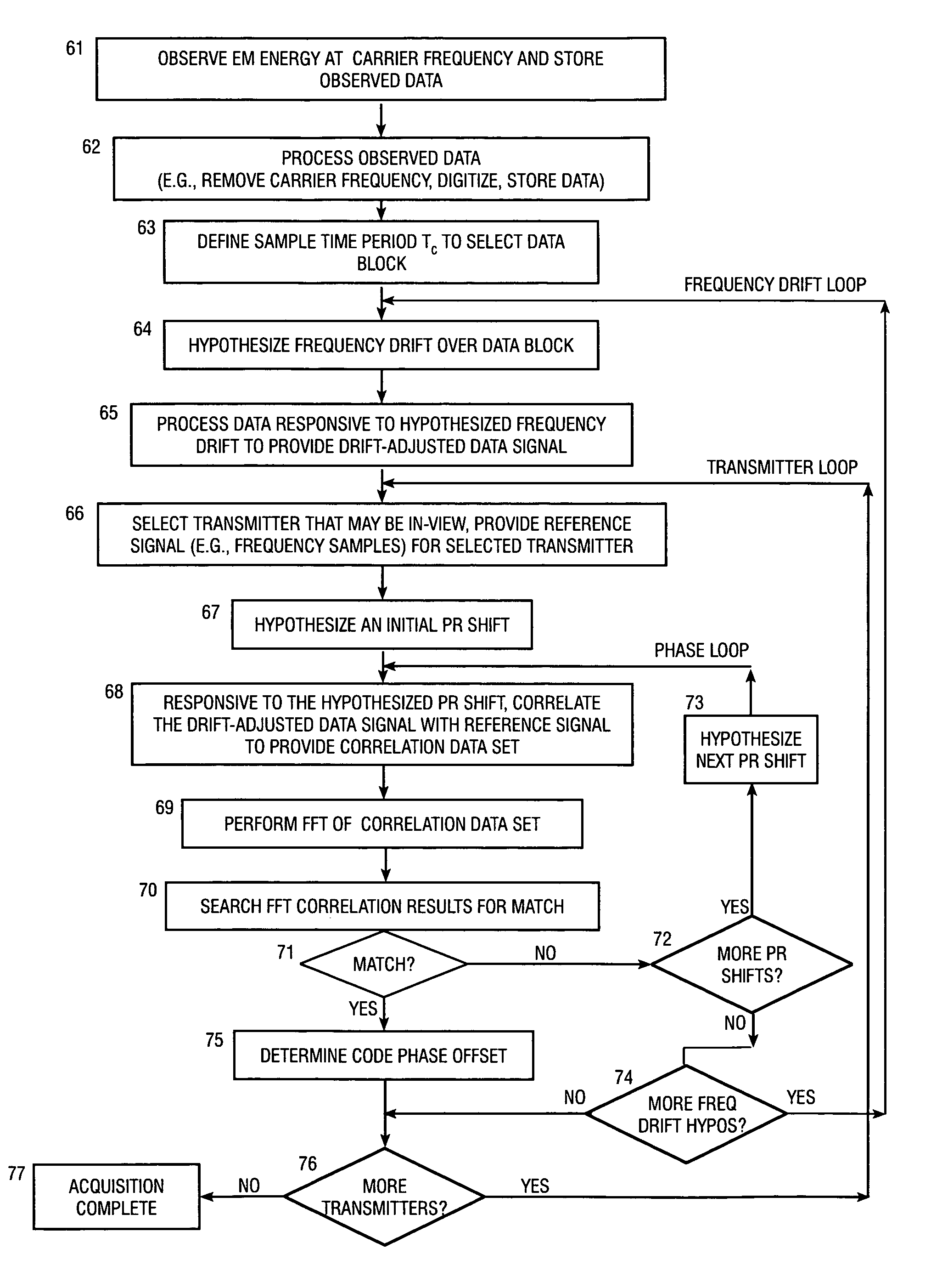
[0027]The FFT and DFT algorithms discussed herein are used to illustrate examples of algorithms that generate frequency samples. More generally, any suitable algorithm that generates appropriate frequency samples may be utilized as an alternative to the FFT and DFT algorithms. For example, the frequency samples may be generated using a DFT-like algorithm where the number and spacing of the frequency domain samples is not exactly that of a DFT; i.e., more or less frequency samples may be computed, and the spacing between the frequency domain samples may be narrower than that of a standard DFT operation. The frequency samples may be generated from digital or analog data, from observed data, or from previously calculated values. The calculated frequency samples are then used for subsequent operations.

Glossary of Terms and Acronyms

[00...


PUM


Abstract

A receiving method and apparatus for increasing coherent integration length while receiving a positioning signal from transmitters such as GPS satellites. In order to compensate for frequency drifts that may occur in the positioning signal, a hypothesis is made as to the frequency drift, which is inserted into the receiving algorithm. Advantageously, the length of coherent integration can be increased at the expense of reducing the length of incoherent integration while keeping the total integration length the same, the net effect of which is an increase in signal detection sensitivity. The frequency drift hypothesis has any appropriate waveform; for example, approximately linear or exponential. The hypothesized frequency drift can be inserted into the receiver algorithm in any suitable place; for example, the data block may be adjusted for the hypothesized frequency drift, alternatively the reference signal may be adjusted, or the frequency samples of either the data block or the reference signal may be adjusted.

Description

BACKGROUND OF THE INVENTION[0001]1. Field of the Invention[0002]This invention relates to apparatus and methods for computing the position of a mobile device by use of wireless positioning signals, such as GPS systems.[0003]2. Description of Related Art[0004]Position location devices are becoming increasingly popular, not only for ships at sea or adventurers in the backcountry, but also for anyone who uses a cell phone in daily life. The increasing number of cell phones, coupled with the popularity of personal position location devices, has encouraged development of rapid, high sensitivity methods for acquiring the signals used to determine position.[0005]Position location technologies typically utilize wireless positioning signals concurrently transmitted from known locations. In GPS systems, these positioning signals are concurrently transmitted from a multiplicity of satellites at a known time, with a predefined frequency. On the ground, a GPS receiver acquires a positioning sign...

Claims


Application Information

Patent Timeline
Patent Type & Authority Patents(United States)
IPC IPC(8): H04L7/00G01S19/09G01S19/23G01S19/29G01S19/46
CPCG01S19/09G01S19/23G01S19/235G01S19/29G01S19/42G01S19/24
Inventor GAAL, PETERPATRICK, CHRISTOPHER
Owner QUALCOMM INC
Why Eureka
Try Eureka