
Network performance monitoring

a network performance and monitoring technology, applied in the field of network performance monitoring, can solve problems such as inability to determine the response time of a transaction or application, and inability to determine the rate of information transmission,

Inactive Publication Date: 2012-08-28
CA TECH INC
View PDF58 Cites 40 Cited by
  • Summary
  • Abstract
  • Description
  • Claims
  • Application Information

AI Technical Summary

Benefits of technology

[0009]The present invention addresses these and other needs by providing in one aspect a method for identifying a transaction corresponding to a plurality of service packets communicated between a source node and a destination node. The method includes the steps: (i) providing a communications data set including a plurality of service packets and information relating to the order in which the service packets are communicated on a communications line between the source and destination nodes and (ii) comparing the communications data set against a pattern characterization data set to determine whether at least a portion of the plurality of service packets are part of the transaction. The pattern characterization data set includes information relating to a predetermined ordering of service packets that comprise the transaction. The method is amenable to non-intrusive / non-invasive measuring techniques and can provide near real-time response time information, even for multi-tiered computer networks.

Problems solved by technology

Even if the applications were to have embedded marker commands, technical problems, can arise due to and consolidation of application-embedded response time statistics to a central location, especially for mobile user computers.
In the case of non-intrusive / non-invasive techniques, it is only possible to determine the rate of information transmission between the computers for individual packets.
Such techniques are typically unable to determine the response time for a transaction or application.
Existing monitoring techniques are unable to match the service packets in the various service requests to a specific transaction.

Method used


Image

  • Network performance monitoring
  • Network performance monitoring
  • Network performance monitoring

Examples


Embodiment Construction

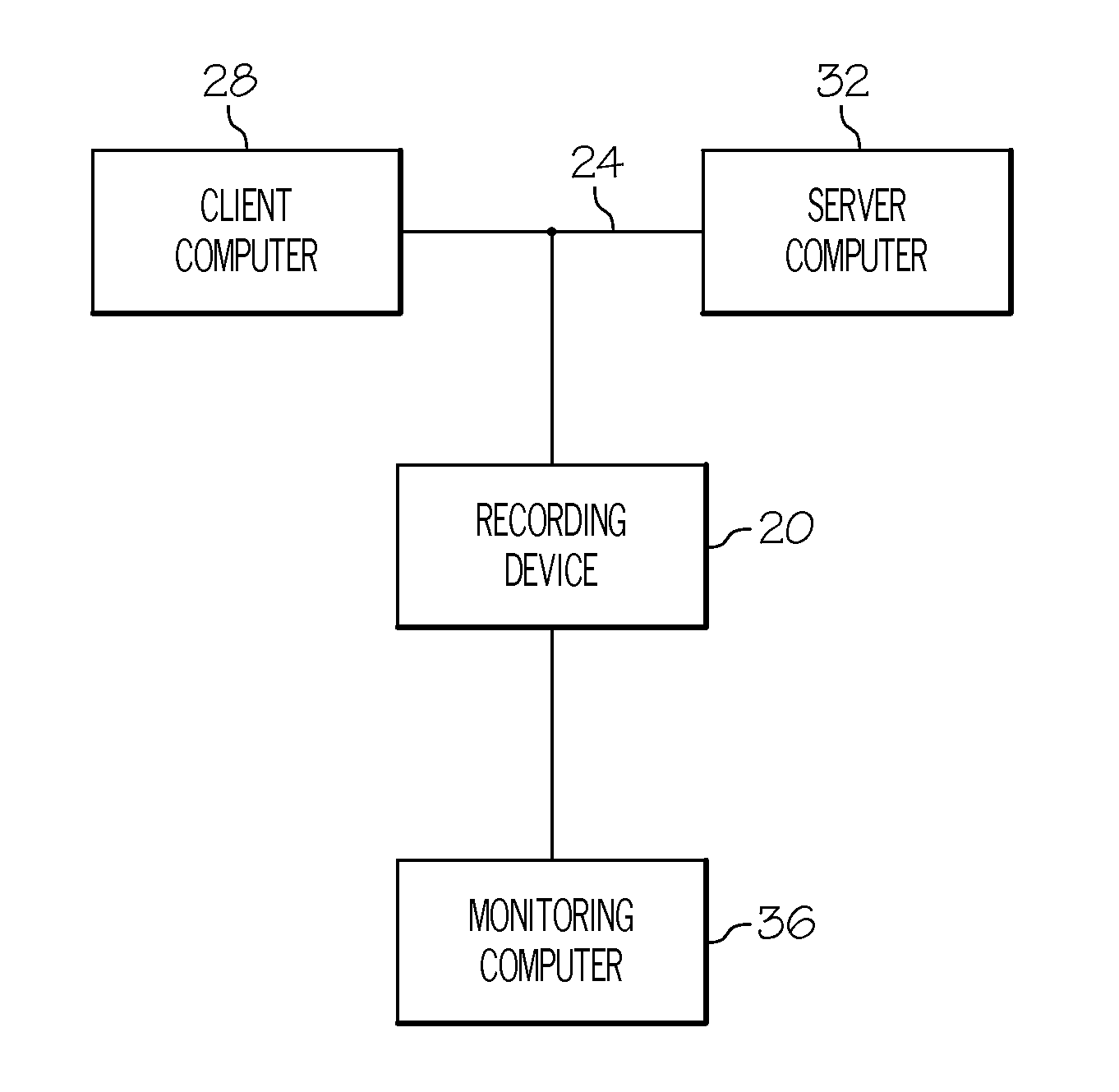
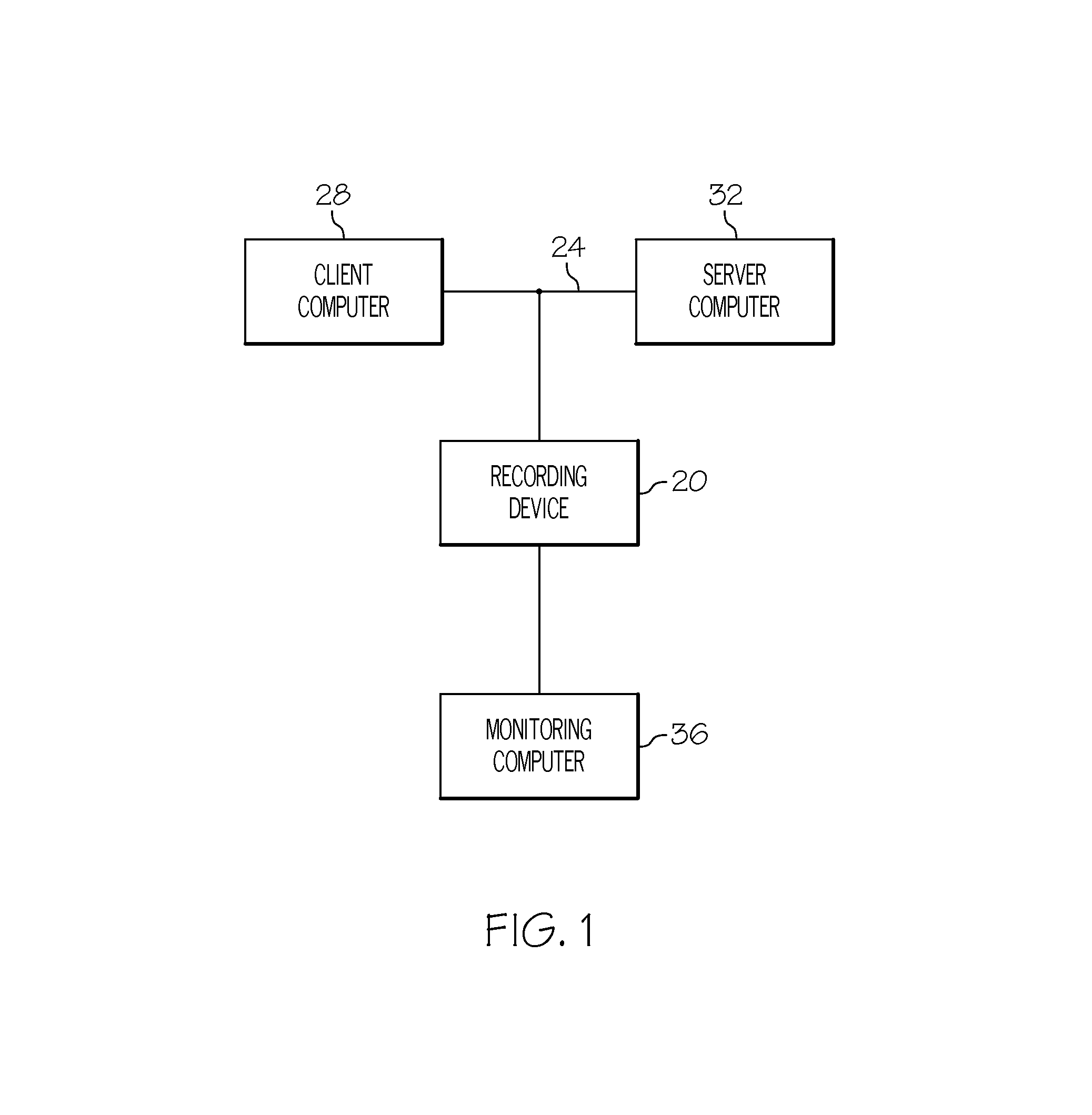
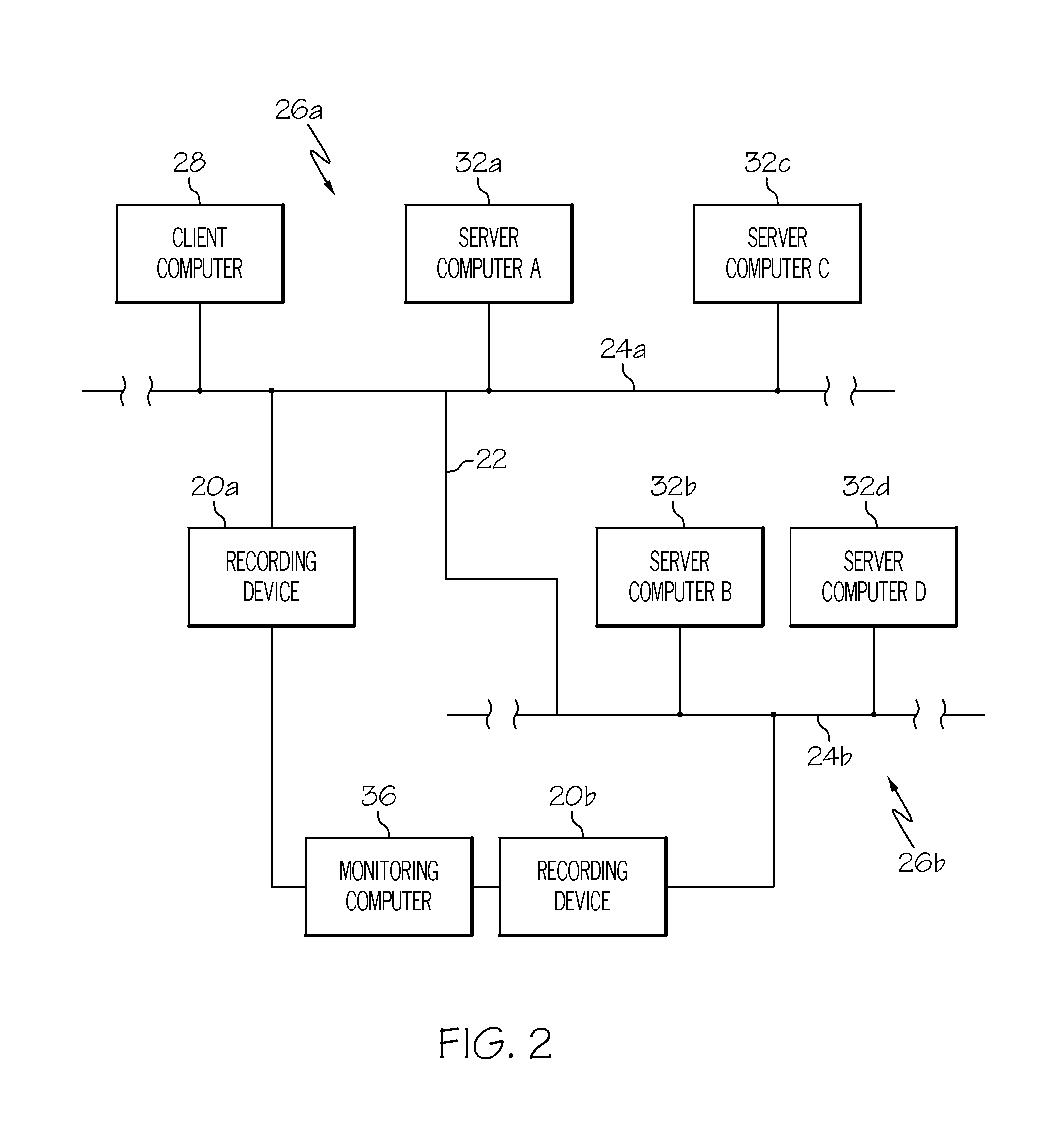
[0032]The present invention is directed to a method and apparatus for measuring response times for a transaction or an application using non-intrusive / non-invasive techniques. As noted above, non-intrusive / non-invasive monitoring techniques do not interrupt the software code to measure response time. Rather, such techniques monitor the network communications between the client computer and the various server computers. Unlike existing performance monitoring methods, the method of the present invention matches selected service packets and associated start and stop time information for the service packets with the corresponding transaction or application. After the matching step, the method provides response times for the transaction or application. The present invention is useful not only for performance monitoring but also for billing and monitoring of service level agreement compliance.

The Apparatus Configuration

[0033]The apparatus configuration according to the present invention i...


PUM


Abstract

The present invention provides a method and apparatus for measuring transaction response times. The method and apparatus can identify service request sequences corresponding to a transaction and the start and stop times for the transaction. The invention can be applied non-intrusively / non-invasively to the service packets communicated between a source and destination node.

Description

CROSS REFERENCE TO RELATED APPLICATIONS[0001]The present application is a continuation of U.S. patent application Ser. No. 09 / 186,906, filed Nov. 5, 1998, now U.S. Pat. No. 6,493,754, which is a continuation of U.S. patent application Ser. No. 09 / 133,069, filed Aug. 12, 1998, now abandoned, which is a continuation of U.S. patent application Ser. No. 09 / 066,508, filed Apr. 23, 1998 (now abandoned), which is a continuation of U.S. patent application Ser. No. 08 / 513,435 filed Aug. 10, 1995 (now issued as U.S. Pat. No. 5,781,449).FIELD OF THE INVENTION[0002]The present invention is directed generally to the measurement of response time in computer applications and specifically to the use of non-intrusive devices to measure response time in multi-tiered computer networks.BACKGROUND OF THE INVENTION[0003]Multi-tiered computer networks are widely used to provide one or more users with a wide variety of information and computer resources. In multi-tiered computer networks, client computers ...

Claims


Application Information

Patent Timeline
Patent Type & Authority Patents(United States)
IPC IPC(8): G06F15/16H04L69/40G06F11/34G06F21/00H04L12/56
CPCG06F11/3419H04L12/2602H04L12/2697H04L41/5054H04L43/00H04L43/50H04L47/283G06F11/3452G06F11/349H04L43/067H04L43/0852H04L43/0864H04L43/12G06F2201/87
Inventor MOORE, STEVEN J.ROSBOROUGH, JAMES M.
Owner CA TECH INC
Learn More