
Sensor shield retention device and system

a technology of retention device and sensor shield, which is applied in the direction of measurement device, measurement apparatus components, instruments, etc., can solve the problems of requiring a relative thick structure for holding the set screw, special tools may be needed, and special tools are easily misplaced

Active Publication Date: 2012-09-04
AIRPORTS AUTHORITY OF INDIA
View PDF11 Cites 4 Cited by
  • Summary
  • Abstract
  • Description
  • Claims
  • Application Information

AI Technical Summary

Benefits of technology

"The present invention provides a shield retention device and a sensor enhancement system that can isolate a sensor from direct impingement. The shield retention device includes a base with multiple petals that flex upon pressure and return to their original position on release of the pressure. The petals have adhesive traps and an overtravel prevention member. The sensor enhancement system includes a mounting shaft with a raised boss and a shield. The shield retention device can be coupled to the mounting shaft and has latches that flex upon pressure and return to original position to secure the shield in place. The latches have an apex cam member that can slide over the raised boss to engage or disengage the shield retention device. The shield retention device also has longitudinal slits that define petals that flex on pressure and return to original position. The petals have petal stops, a shield bonding mechanism, an overtravel prevention member, and an apex cam member. The technical effects of the invention include isolating sensors from direct impingement and improving sensor performance."

Problems solved by technology

Primary disadvantages of using such setscrews includes the fact that a relatively thick structure to hold the setscrew may be required, and a special tool may be needed when attaching and removing windscreens in the field.
Such special tools are readily misplaced and may be difficult to obtain in certain remote areas, particularly in combat and other demanding conditions.
Tiny setscrews are easily damaged, often lost, and may be difficult to replace in the field.
An obvious disadvantage to using plastic cable ties in the field is their poor resistance to sunlight, unless the plastic is pigmented black, and / or ultraviolet inhibited.
Furthermore, most plastic ties are not reusable, and have to be cut off and discarded when changing a windscreen.
In addition, cable ties are only applicable to relatively narrow-shaped, elongated windscreens, since larger ball-shaped windscreens would have no such neck for the wire tie to readily attach.
For example, although it may be feasible to manufacture a large ball-shaped windscreen having a narrow neck, such a windscreen would be cost prohibitive and highly wasteful of material, and would likely be manufactured in two pieces.
However, ball locks are fairy expensive, and require substantial housings for proper installation.
Furthermore, a ball lock by itself would not provide any positive over travel limit.
Should the windscreen touch the surface of the microphone, then unwanted noise could easily be generated, by inadvertent contact and rubbing of the two surfaces, especially under the influence of dynamic motion and / or windy conditions.
A frictional interface is not considered reliable when subjected to the external forces of high wind and rain, jolting over rugged terrain, or in the presence of rough handling environments such as inadvertent contact with foliage and brush when mounted on a moving vehicle, as expected in many military environments.
Furthermore, the use of frictional, drawstring, or cable tie type attachments do not provide a positive means to achieve axial location of the windscreen along the microphone's stem.
Knowing that it is highly desirable for acoustic reasons to not bottom the windscreen directly against the microphone, as mentioned above, the lack of a positive positioning feature can be deleterious to the microphone's desired performance.

Method used


Image

  • Sensor shield retention device and system
  • Sensor shield retention device and system
  • Sensor shield retention device and system

Examples


Embodiment Construction

[0026]Various exemplary embodiments are discussed in detail below including a preferred embodiment. While specific implementations are discussed, it should be understood that this is done for illustration purposes only. A person skilled in the relevant art can recognize that the systems, methods and features provided herein may be used without parting from the spirit and scope of the invention. Furthermore, any and all references cited herein shall be incorporated herein by reference in their respective entireties.

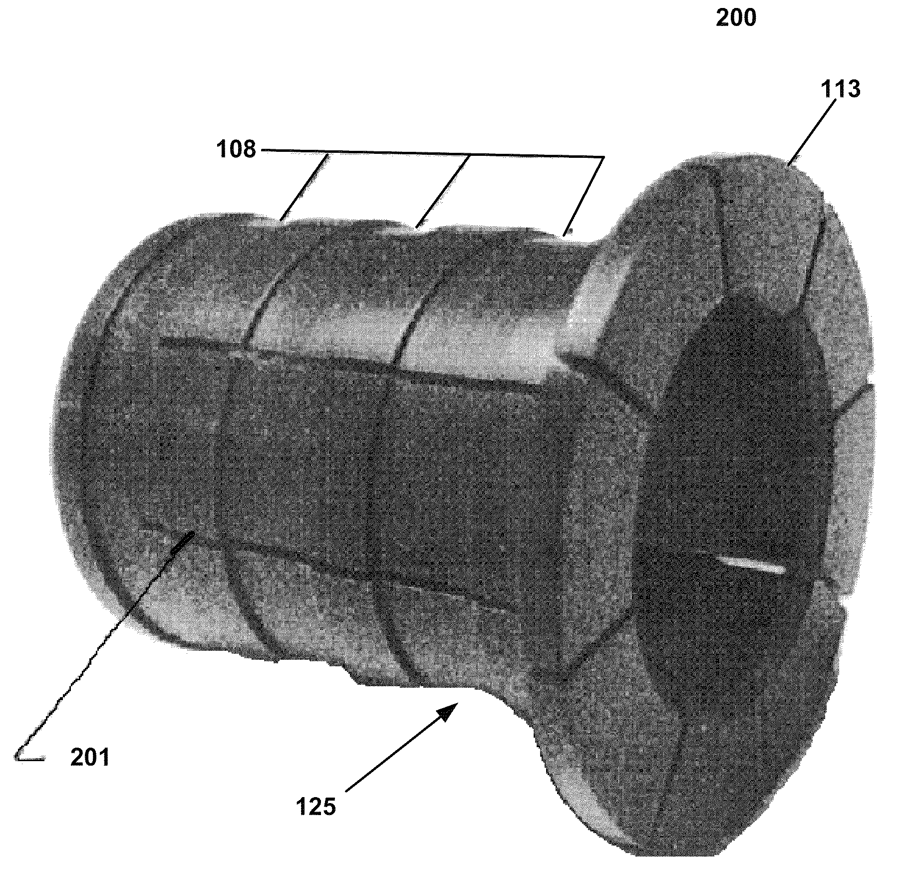
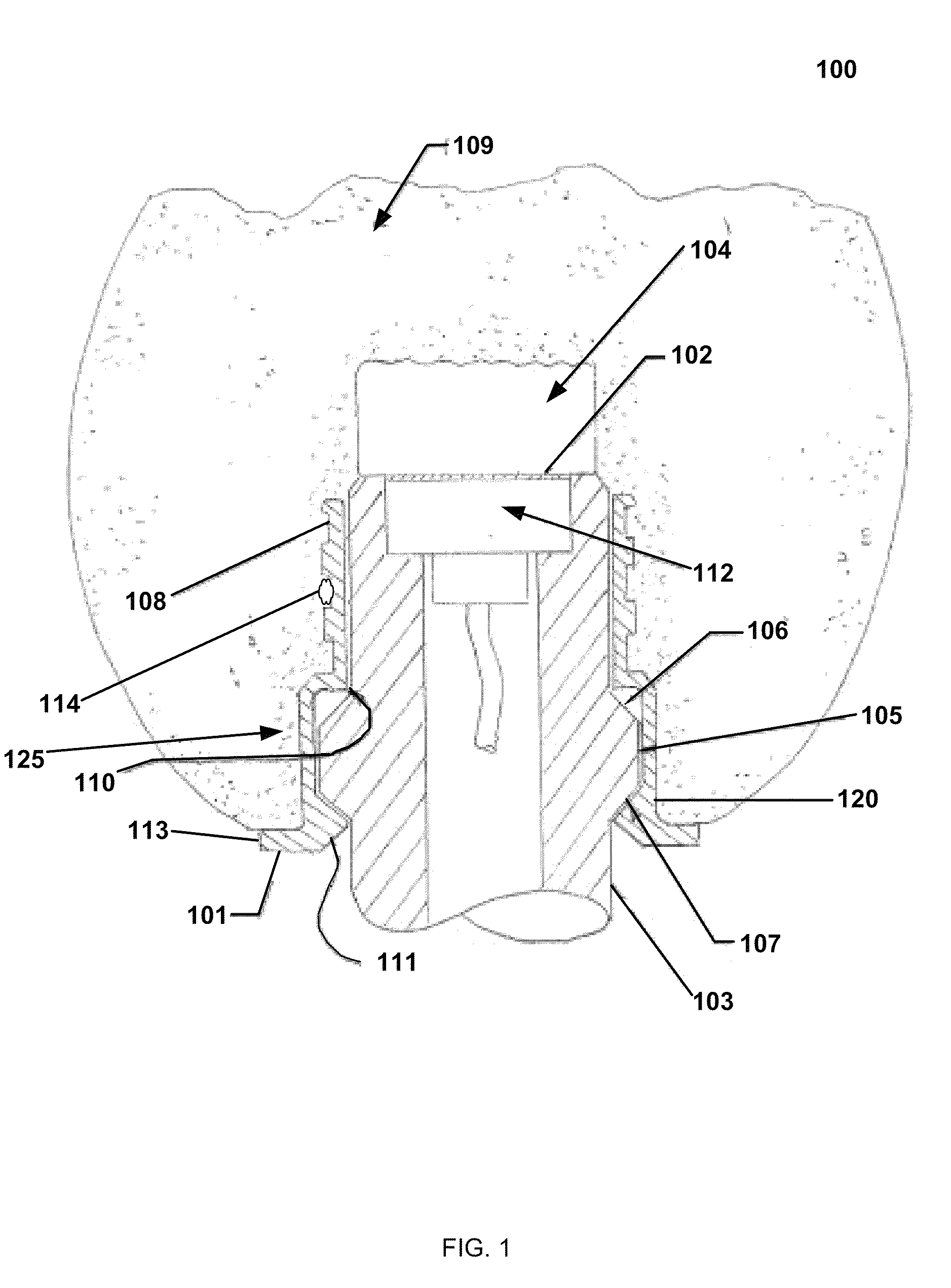
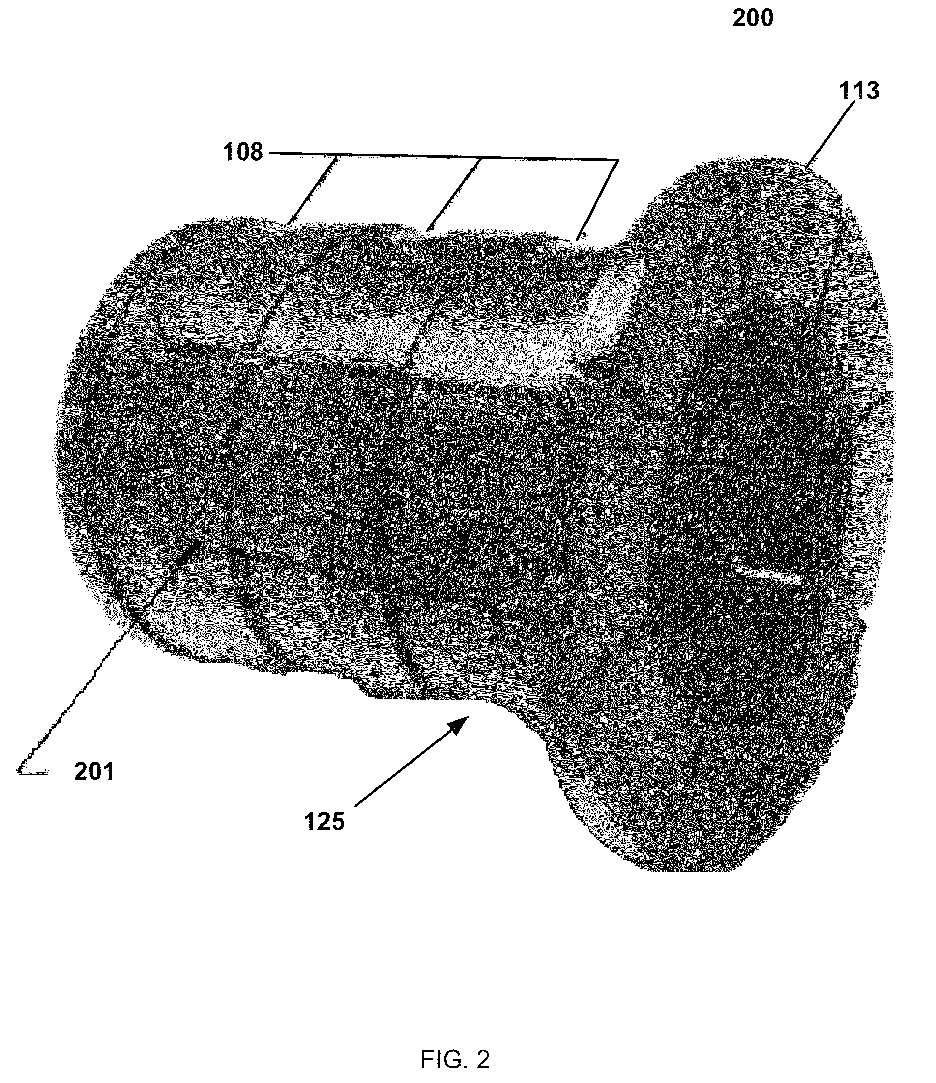
[0027]FIG. 1 (view 100) depicts an exemplary embodiment of the invention in one configuration. Item 112, a sensor or detector, such as, but not limited to, a microphone, temperature sensor, humidity sensor, smoke detector, gas detector, seismometer, Geiger counter, chemical sensor, etc., is typically mounted on the nose of a sensor mounting shaft, item 103. The sensor may have, for example, a metallic screen attached to its face, item 102. The sensor, item 112, may be prot...


PUM

PropertyMeasurementUnit
45 degree anglesaaaaaaaaaa
degree anglesaaaaaaaaaa
temperatureaaaaaaaaaa

Abstract

A system and device that provides for the retention of a sensor shield for a sensor such as a microphone, hydrometer, chemical sensor, or other detector. This invention provides for the quick attachment and release of a reduced visibility and reduced bulk shield retention assembly. In a battlefield environment, a smaller profile sensor shield presents less visibility as a prospective target of interest to enemy forces. Also, the sensor shield may be readily replaced without the use of any tools. The snap-lock feature provides a positive means for holding, for example, a windscreen in its respective position, requiring reasonable, but yet not objectionable force to install and remove the windscreen from the sensor's mounting shaft. Furthermore, the snap-lock feature, when engaged, may provide positive location of the sensor shield's sweet spot by maintaining a slight air space between the sensor shield and the sensor, and thereby precluding direct physical contact.

Description

PRIORITY DATA[0001]This application claims the benefit of U.S. Provisional Application No. 61 / 169,653, filed Apr. 15, 2009, which is hereby incorporated by reference.BACKGROUND[0002]1. Field[0003]Exemplary embodiments relate generally to sensor shields such as windscreens for microphones or other sensors.[0004]2. Related Art[0005]Working microphones and other sensitive equipment used in the field may require protection from the elements. For example, ultra-sensitive gunfire detection equipment, including the Projectile Detection and Cueing (PDCue®) Tetrahedral and Packbot designs, by AAI Corporation, include microphones which may desirably employ windscreens and analogous equipment.[0006]These windscreens may employ mechanisms for attachment. For example, miniature setscrews may be used to attach the windscreens to microphone posts. Primary disadvantages of using such setscrews includes the fact that a relatively thick structure to hold the setscrew may be required, and a special to...

Claims


Application Information

Patent Timeline
Patent Type & Authority Patents(United States)
IPC IPC(8): G01D11/24G01L19/14
CPCG01D11/30
Inventor KARMAZYN, MICHAEL J.
Owner AIRPORTS AUTHORITY OF INDIA
Learn More