Suspension assembly

a suspension system and assembly technology, applied in mechanical equipment, liquid springs, transportation and packaging, etc., can solve the problems of low torque on the axle tube, and achieve the effects of good ride, excellent stability, and the ability to raise and lower the trailer

Active Publication Date: 2012-09-04
TRANSPORTATION TECH
View PDF39 Cites 8 Cited by
  • Summary
  • Abstract
  • Description
  • Claims
  • Application Information

AI Technical Summary

Benefits of technology

[0012]Thus, in accordance with one of the main features of the present invention, the short distances between the air spring support arm pivot axis and the torsion axle axis, and to the centerline of the air spring provides a vehicle suspension assembly which is of a compact and sturdy construction, which is adapted to be secured to the vehicle frame of the vehicle and supports one end of a torsion axle which extends across the vehicle between the spaced vehicle wheels, and which has a stub shaft pivotally mounted by elastomeric members within the interior of the torsion axle at each end of the axle, wherein the stub shaft is attached at an outer end to a spindle arm and has an air spring extending between the frame mounting bracket and the distal end of a mounting lever.
[0013]The improved suspension assembly provides good ride, excellent stability, axle-to-axle equalization and the ability to raise and lower the trailer for easier loading and unloading. Also, the combination of rubber and air in series provided by the torsion axle and air spring, respectively, ensures that the vehicle has some suspension and isolation even if the air system is not inflated or fails for any reason. Furthermore, the axle-to-axle equalization allows the use of torsion axles on multi-axle trailers that currently allow only single axle and tandem axle applications. The compact design is easily adaptable for capacities from 2,300 lbs to over 10,000 lbs. If desired, optional shock absorbers, air controls etc. can be incorporated easily into the final suspension assembly.

Problems solved by technology

This results in lower torque on the axle tube in roll or diagonal walk or tramp.

Method used


Image

  • Suspension assembly
  • Suspension assembly
  • Suspension assembly

Examples


second embodiment

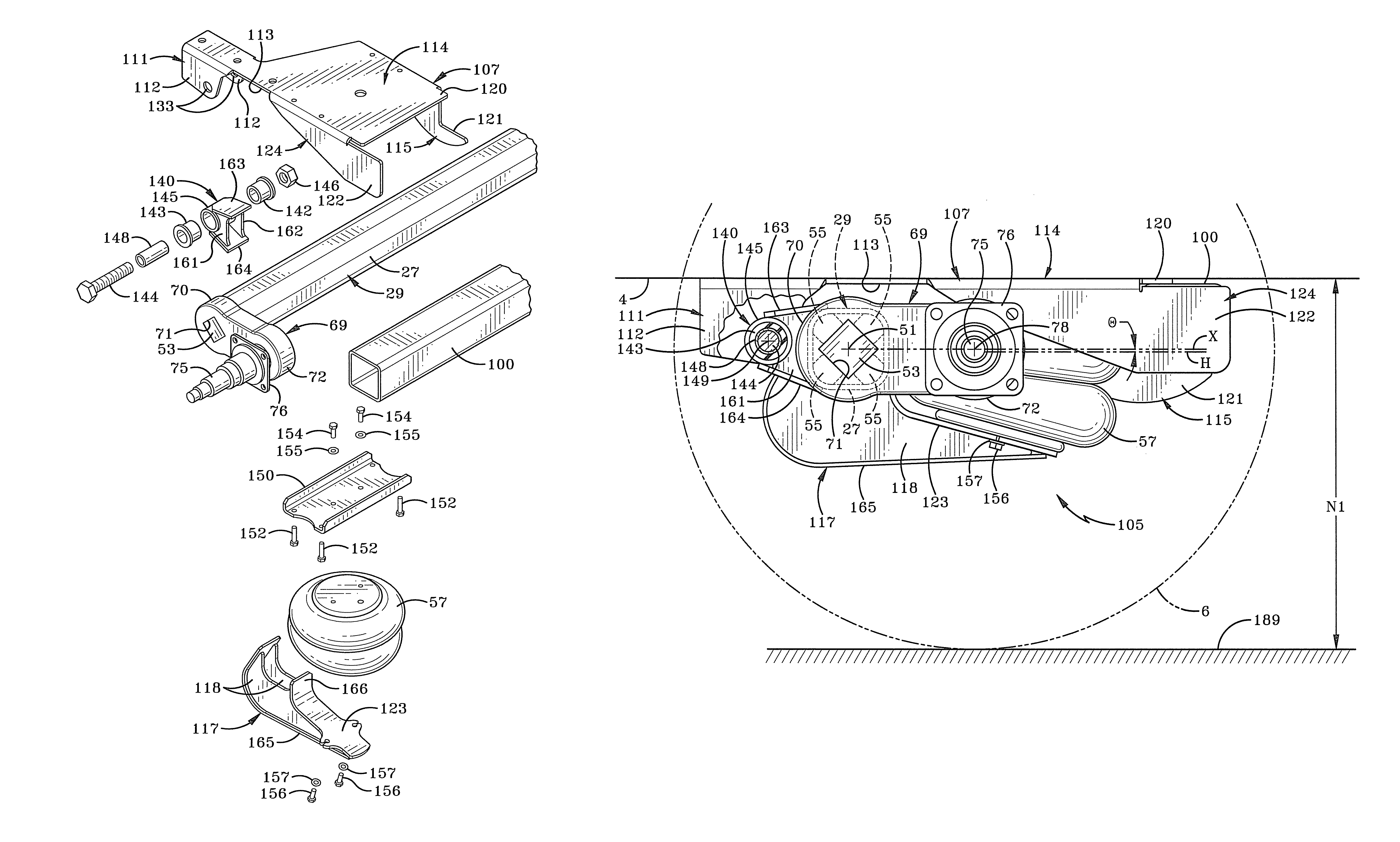
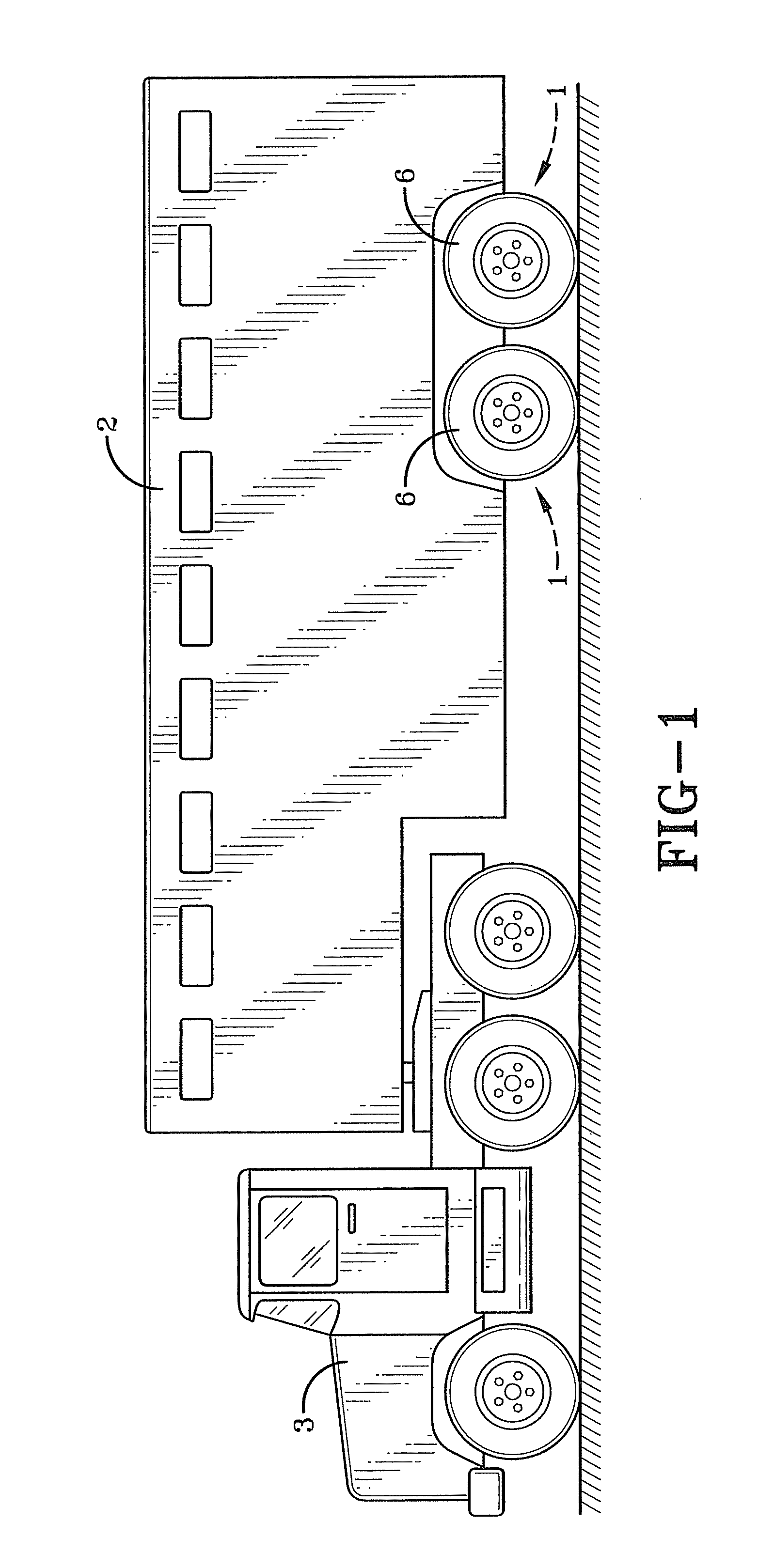
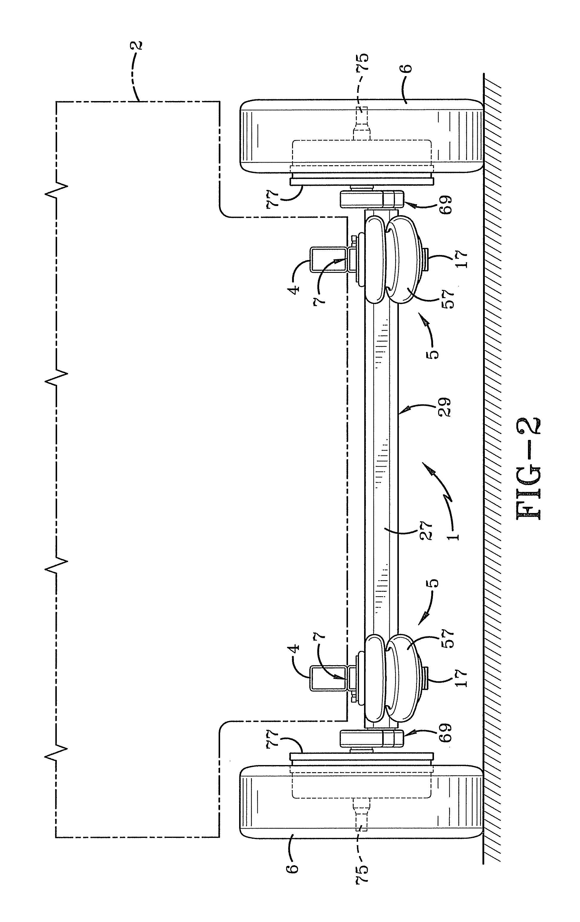
[0075]FIG. 22C shows the suspension system 1 under no load condition without air in the air spring 57. This suspension assembly 105 may be operated without air (or with reduced air) in the air springs to lower the trailer 2 to match the height of a loading dock or to pass under an overhead obstacle. The distance from the bottom of the trailer 2 to the ground 189 with no air in the air spring 57 is N3 which is less than the distances N1 and N2 of FIGS. 22A and 22B when there is air in the air spring 57 in the design position.

[0076]The manner of operation of the second embodiment of the suspension assembly 105 is best shown in FIGS. 22-27. FIGS. 22A and 25 show the suspension assembly 105 in the design position when there is no load acting on the suspension assembly 105. FIG. 26A shows the position of the air spring 57 and the support arm 117 in the design position at the start of a jounce movement whereas only a rotational force indicated by Arrow R, is applied to the stub shaft 53 t...

third embodiment

[0079]FIG. 28 shows a suspension assembly 105 with a cross-member attachment device 99 attached to the frame mounting bracket 107. The cross-member attachment device 99 may be a cylindrical cross-member attachment device 101 as shown in FIG. 28. The cylindrical cross-member attachment device 101 may be welded to the frame mounting bracket 107 or attached to the frame mounting bracket 107 by another means as understood by those of ordinary skill in the art. The cylindrical cross-member attachment device 101 is adapted to receive a cylindrical cross-member brace 104 allow for easy installation of the suspension assembly 105 to a trailer 2. For example, the cross-member attachment device 99 and more specifically the tubular cylindrical attachment device 104 may have an opening 90 into an interior chamber. The cross-member attachment device 99 is adapted to have an end portion of the cross-member brace 100 slid through the opening 90 into the chamber. The cross-member attachment device ...


PUM


Abstract

A vehicle suspension system includes a frame mounting bracket. A torsion axle is pivotally attached to the frame mounting bracket. The torsion axle pivots about a suspension assembly pivot axis. An air spring support arm is rigidly attached to the torsion axle. An air spring is attached at one end to the frame mounting bracket and at an end of the support arm opposite the suspension assembly pivot axis. A spindle arm with a spindle is adapted for mounting a wheel assembly is attached to the torsion axle. The vehicle suspension system is adapted to include an optional cross-member brace adapted to attach to the frame mounting bracket allowing the cross-member brace to extend across a width of a vehicle to an adjacent vehicle suspension assembly.

Description

CLAIM FOR PRIORITY[0001]This application is a continuation-in-part of U.S. patent application Ser. No. 12 / 117,366 filed May 8, 2008; the disclosure of which is incorporated herein by reference.BACKGROUND OF THE INVENTION[0002]1. Technical Field[0003]The invention relates to suspension systems for vehicles, such as trailers and trucks. More particularly, the invention relates to a suspension assembly having a torsion axle in combination with an air spring. Even more particularly, the invention relates to a more compact, lighter weight combination torsion axle—air spring suspension assembly than known prior art combination suspension assemblies.[0004]2. Background Information[0005]Torsion axles have been known for many years, such as shown in U.S. Pat. No. 2,998,981. Torsion axles have proven to be extremely popular because if one wheel hits a bump or rut, it can react independently of the other wheel, which may not hit a bump or rut at the same time. This torsion axle concept operate...

Claims


Application Information

Patent Timeline
Patent Type & Authority Patents(United States)
IPC IPC(8): B60G11/18
CPCB60G11/225B60G11/62B60G2200/132B60G2200/31B60G2202/1424B60G2202/152B60G2204/125B60G2204/126B60G2204/143B60G2204/148B60G2204/41B60G2204/4302B60G2300/04
Inventor VANDENBERG, ERVIN K.CROSTON, DAVID H.
Owner TRANSPORTATION TECH
Why Eureka
Try Eureka