
Vehicle body structure

a technology for vehicles and body parts, applied in the direction of superstructure sub-units, monocoque structures, roofs, etc., to achieve the effect of reducing constraints and improving design freedom

Active Publication Date: 2012-09-04
NISSAN MOTOR CO LTD
View PDF17 Cites 20 Cited by
  • Summary
  • Abstract
  • Description
  • Claims
  • Application Information

AI Technical Summary

Benefits of technology

[0005]One object of the present disclosure is to provide a vehicle body structure that improves design freedom by reducing constraints that limit the positioning of roof ditches with respect to outer door edges.
[0006]Another object of the present disclosure is to provide a vehicle body structure that increases interior roominess by utilizing the roof ditch as a hinge mounting location.
[0007]Still another object of the present disclosure is to provide a vehicle body structure that reduces the need for reinforcement panels.
[0008]Still another object of the present disclosure is to provide a vehicle body structure that increases torsional rigidity of the overall door assembly.

Problems solved by technology

Typically, such lift gates are heavy, and thus, the lift gate be mounted to a strong structural portion of the vehicle.
Also, the hinge assemblies can be mounted to the side edges of the lift gate so that are not readily visible when the lift gate is closed.

Method used


Image

  • Vehicle body structure
  • Vehicle body structure
  • Vehicle body structure

Examples


Embodiment Construction

[0029]Selected embodiments will now be explained with reference to the drawings. It will be apparent to those skilled in the art from this disclosure that the following descriptions of the embodiments are provided for illustration only and not for the purpose of limiting the invention as defined by the appended claims and their equivalents.

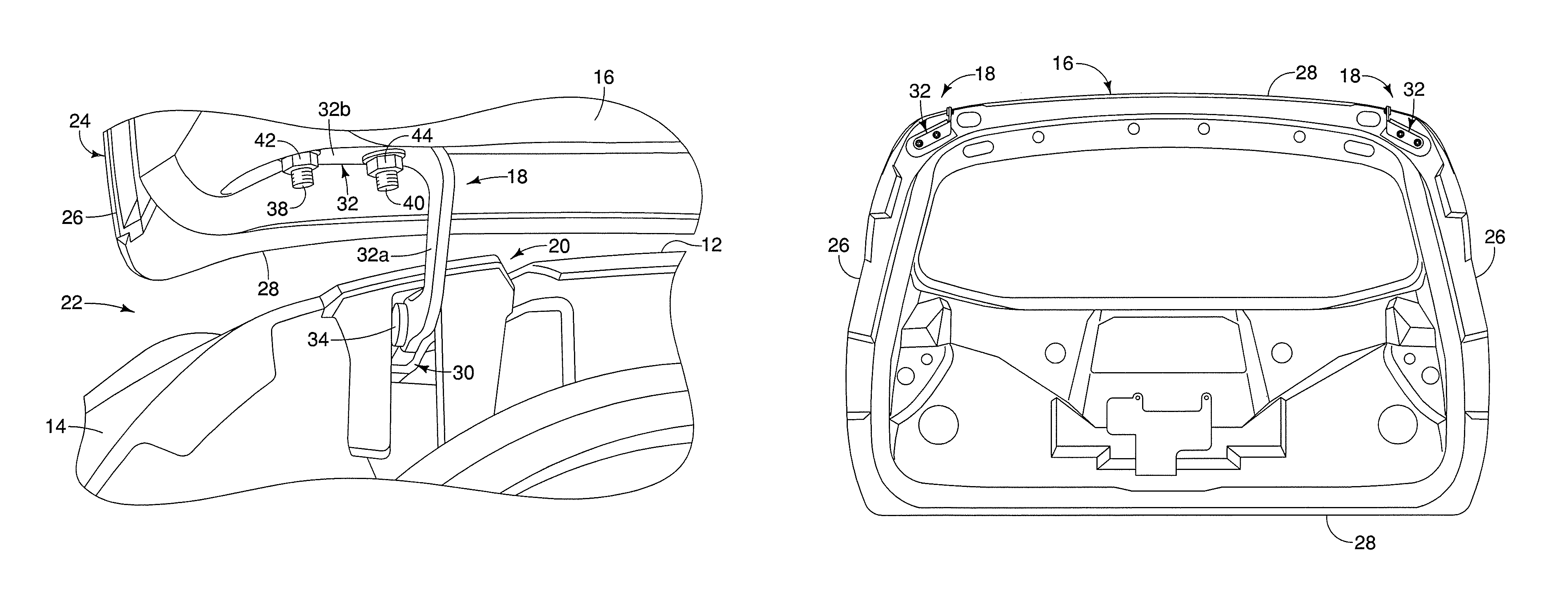
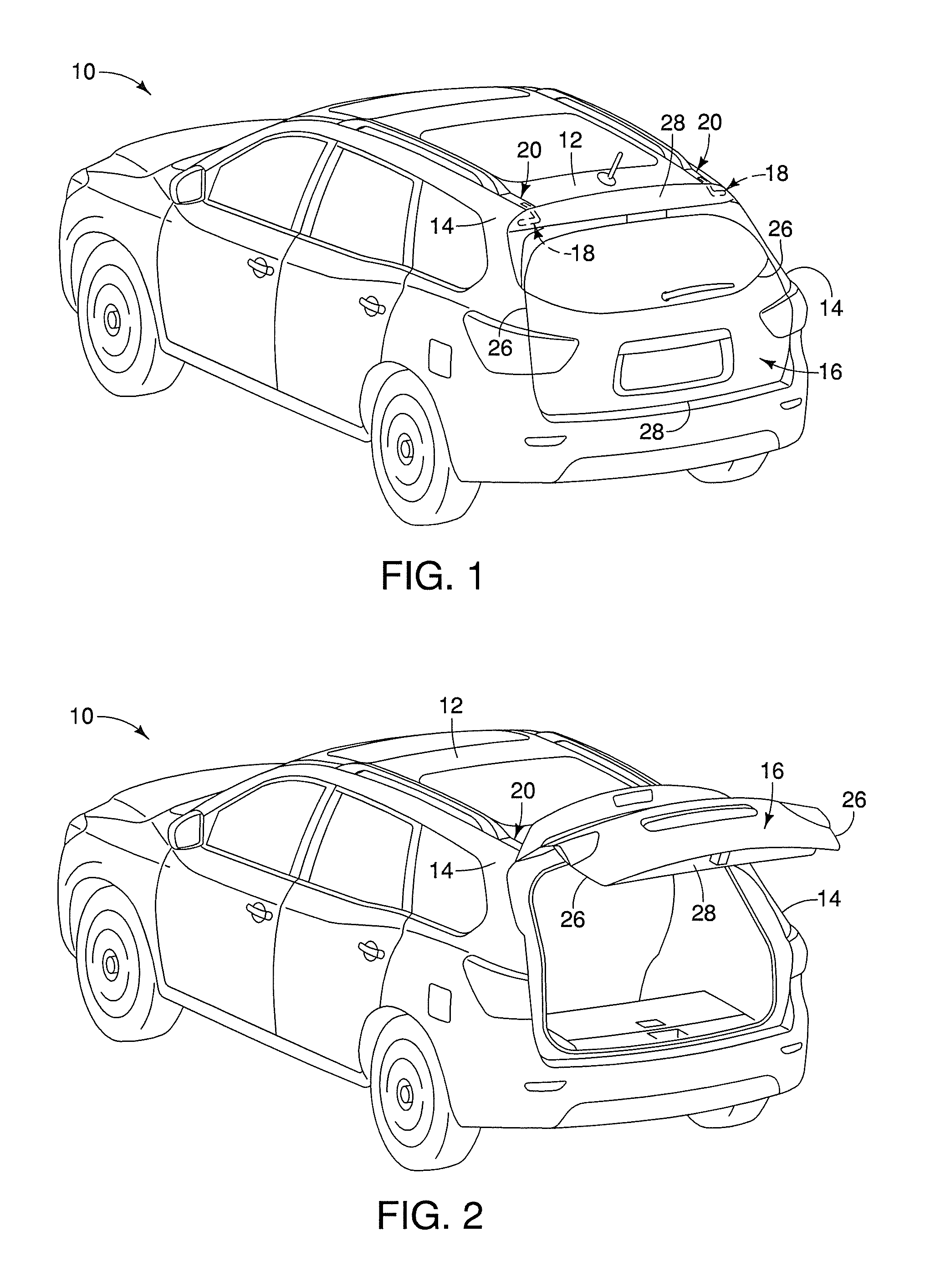
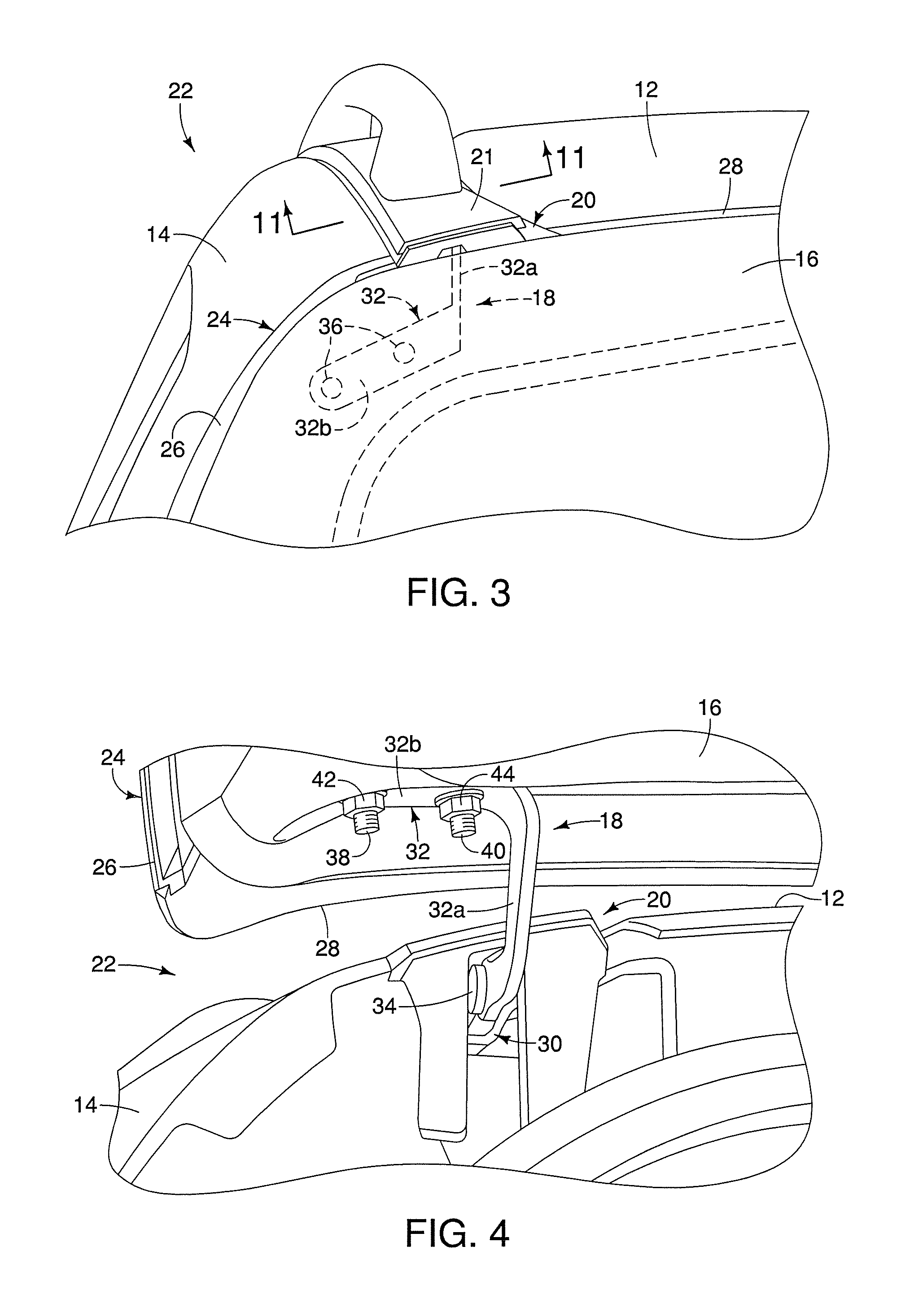
[0030]Referring initially to FIGS. 1 and 2, a vehicle 10 is illustrated in accordance with a first embodiment. The vehicle 10 includes, among other things, a roof panel 12 and a pair of side panels 14 that together with other panels form a vehicle body. The roof panel 12 and the side panels 14 are typically formed of one or more pieces of sheet metal or any other suitable material that is welded together to form a substantially rigid portion of the vehicle body. Also the roof panel 12 and / or the side panels 14 can be supported by other structural members as needed and / or desired. The vehicle 10 also includes a vehicle door 16 that is typically for...


PUM


Abstract

A vehicle body structure comprises at least one vehicle body panel, a hinge and a vehicle door. The vehicle body panel includes a roof ditch that is defined by a recessed support surface, a first wall surface and a second wall surface. The second wall surface is disposed outboard of the first wall surface. The hinge includes a base component and an arm component. The arm component is pivotally coupled to the base component. The base component is mounted to the recessed support surface of the roof ditch. The arm component includes a vehicle door mounting structure. The vehicle door is fixed to the arm component by the vehicle door mounting structure, which defines at least one fastening point that is situated at a location outboard of the second wall surface of the roof ditch.

Description

BACKGROUND[0001]1. Field of the Invention[0002]The present invention generally relates to a vehicle body structure. More specifically, the present invention relates to a vehicle body structure having a mounting arrangement for pivotally coupling a vehicle door to a vehicle body.[0003]2. Background Information[0004]Many vehicles such as station wagons, support utility vehicles and mini vans include a rear door (e.g., a tailgate or a lift gate) that is pivotally mounted to pivot about horizontal axes in order to access a rear cargo space. Such rear doors are typically mounted to the vehicle body by a pair of lift gate hinge assemblies located at the top end of the lift gate. Typically, such lift gates are heavy, and thus, the lift gate be mounted to a strong structural portion of the vehicle. In most cases, the lift gate hinge assemblies are mounted at the rear end of the vehicle roof. In some vehicles, the lift gate hinge assemblies are mounted to an exterior surface of the vehicle r...

Claims


Application Information

Patent Timeline
Patent Type & Authority Patents(United States)
IPC IPC(8): B60J5/10
CPCB60J5/101B62D25/07
Inventor DRYJA, RICHARD J
Owner NISSAN MOTOR CO LTD
Learn More