Variable displacement vane pump
a vane pump and variable displacement technology, applied in the direction of machines/engines, positive displacement liquid engines, liquid fuel engines, etc., can solve the problems of pressure plate deformation, increase the axial thickness of the pressure plate, prevent undesired deformation, and increase the size and weight of the vane pump
- Summary
- Abstract
- Description
- Claims
- Application Information
AI Technical Summary
Benefits of technology
Problems solved by technology
Method used
Image

Examples
first embodiment
[0021]FIGS. 1˜12 are views for showing a variable displacement vane pump according to a first embodiment of the present invention.
[0022][Outline of Variable Displacement Vane Pump]
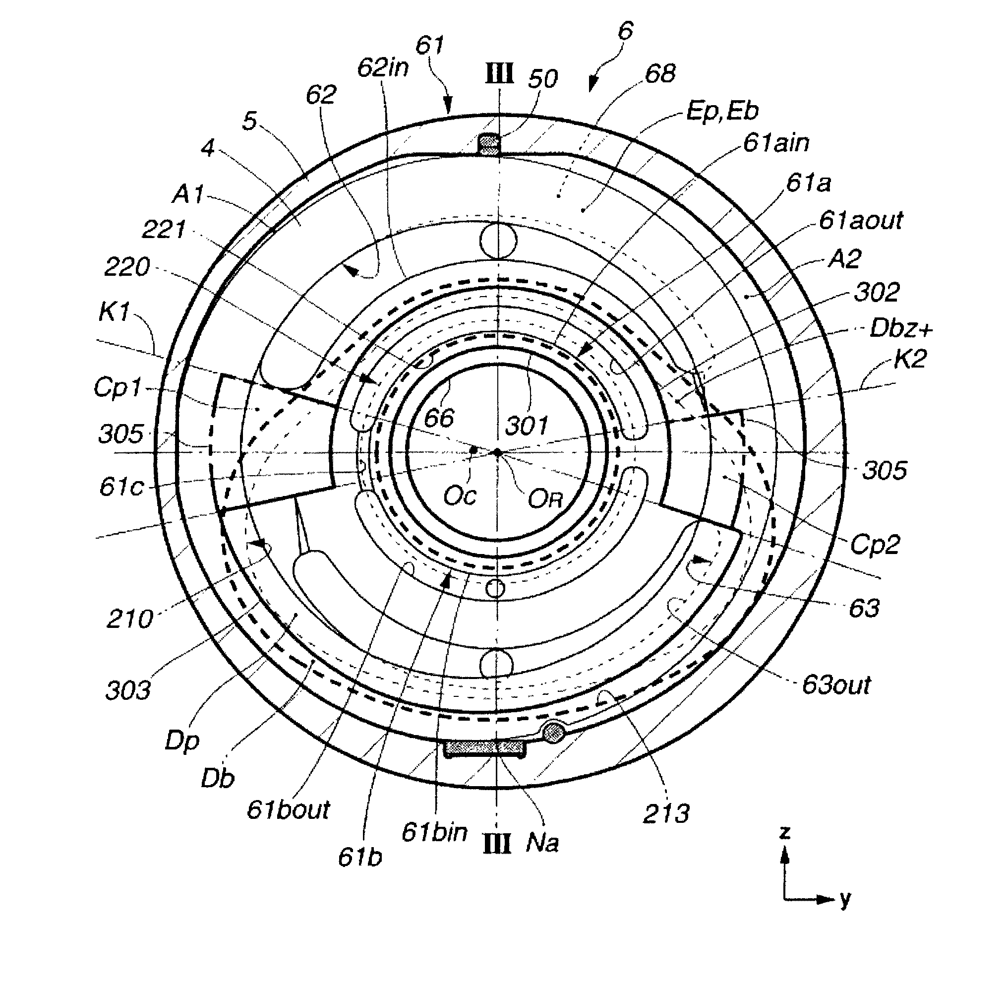
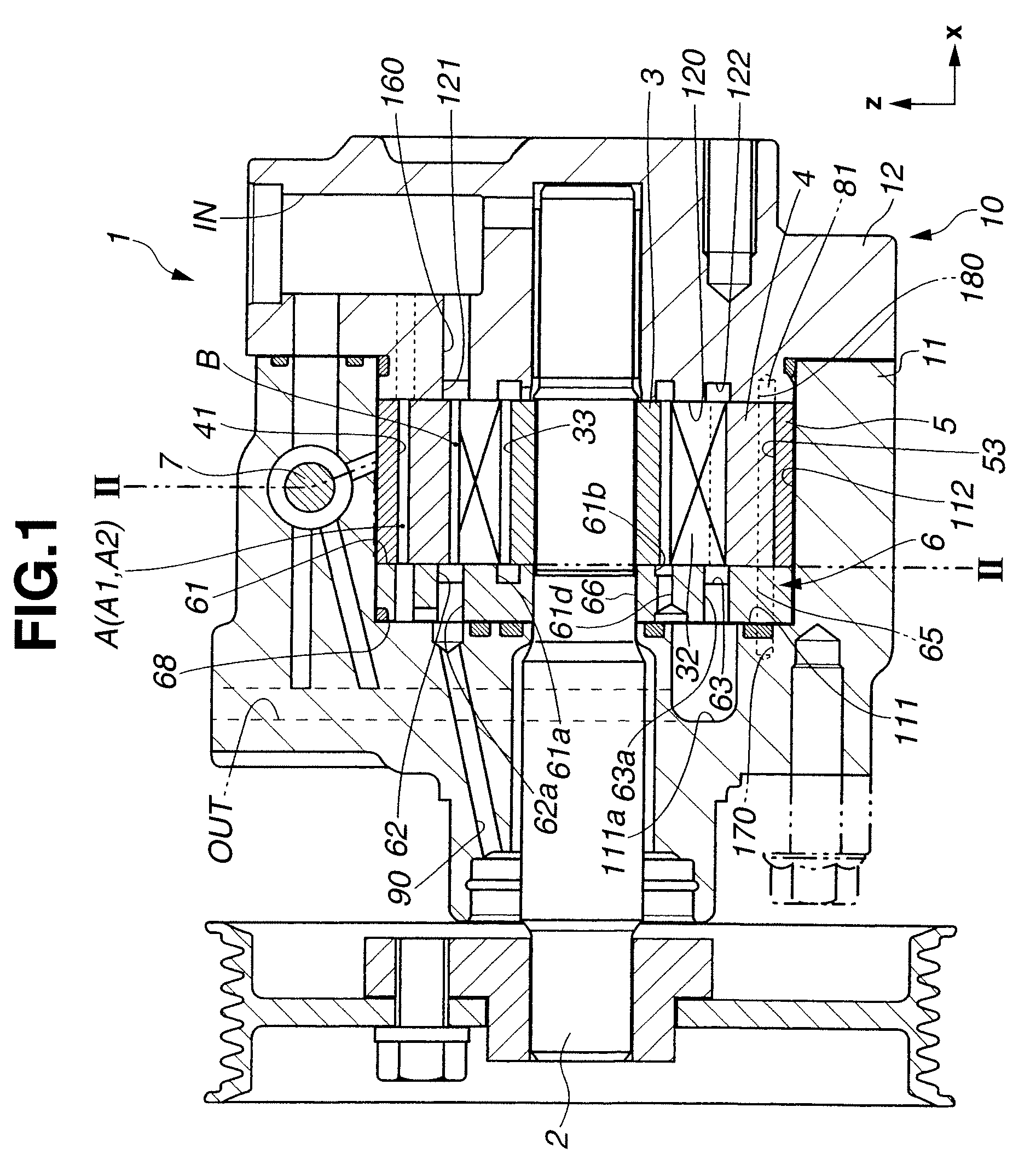
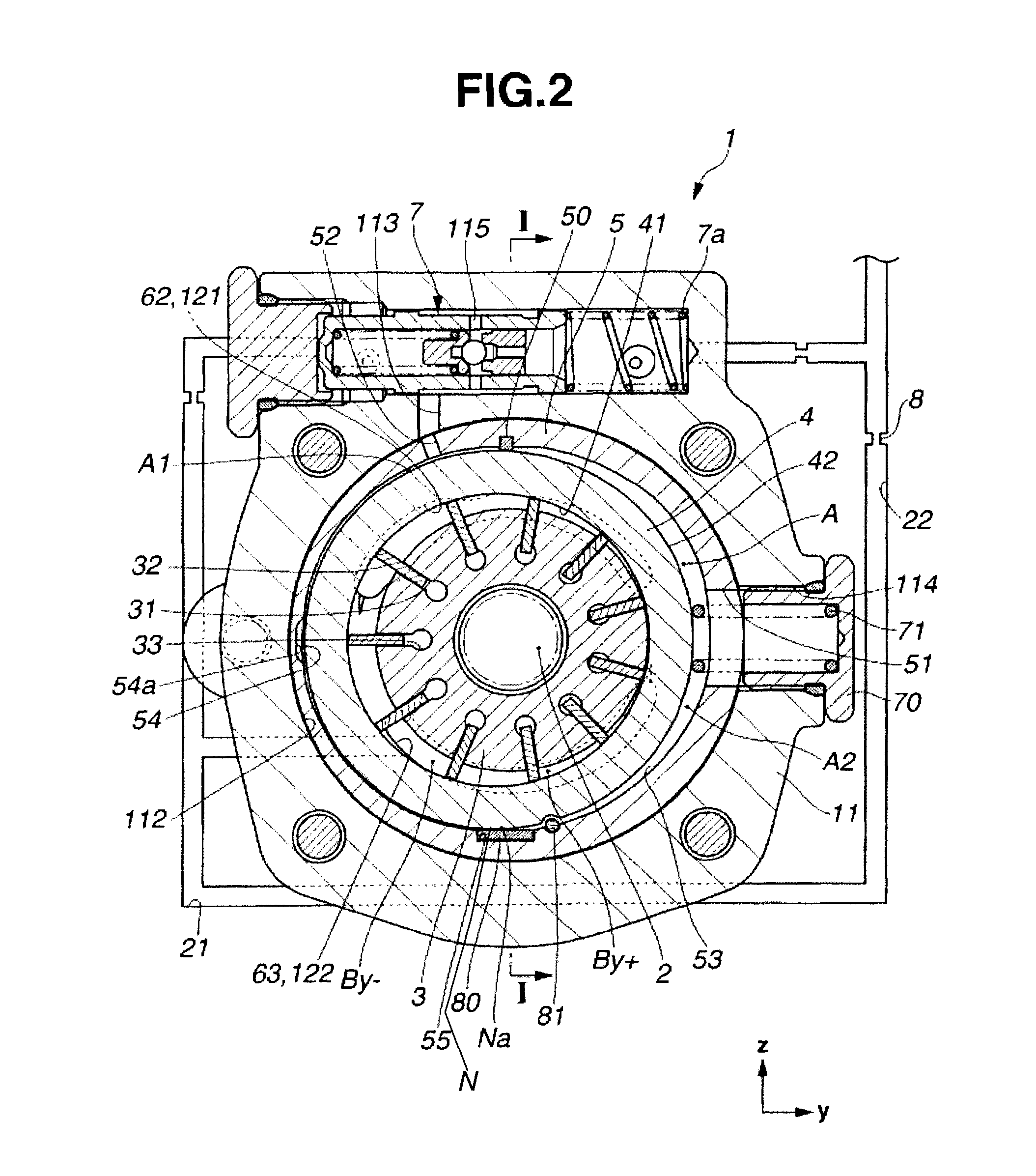
[0023]FIG. 1 shows, in the form of an axial section (taken across a line I-I of FIG. 2), a variable displacement vane pump 1 according to the first embodiment of the present invention. FIG. 2 is a radial section (taken across a line II-II shown in FIG. 1) in a maximum eccentricity state in which a cam ring 4 is shifted most in a negative y direction. FIG. 3 is a front view showing a positive x side of a front body 11 together with seal members 210, 220 and 67.
[0024]The following explanation uses an orthogonal coordinate system including an x-axis extending in an axial direction of a drive shaft 2 of the vane pump 1, a y-axis extending in an axial direction of a spring 71 (shown in FIG. 2) for regulating swing motion of cam ring 4, and a z-axis orthogonal to the x-axis and y-axis. A positive x direction (ri...
second embodiment
[0117]FIGS. 13 and 14 are views for showing a variable displacement vane pump according to a second embodiment of the present invention. The basic structure of the vane pump 1 of the second embodiment is identical to that of the first embodiment. In the second embodiment, however, the first seal member 210 is offset from a median plane III-III containing the center axis (OR). FIG. 13 shows the sliding surface 61 of pressure plate 6 according to the second embodiment on the positive x side, and FIG. 14 shows the first seal member 210. In FIG. 13, first seal member 210 is shown by a solid line for clarification though it is disposed on the negative x side (backup surface 68) of pressure plate 6, and the second seal member 220 is omitted because second seal member 220 is arranged symmetrically with respect to the median plane III-III as in the first embodiment.
[0118]As shown in FIG. 13, first seal member 210 is arranged symmetrically with respect to an offset plane IV-IV which is paral...
third embodiment
[0123]FIG. 15 is a view for showing a variable displacement vane pump according to a third embodiment of the present invention. The basic structure of the vane pump 1 of the third embodiment is identical to that of the second embodiment. In the third embodiment, however, the first seal member 210 is asymmetric. FIG. 15 shows the sliding surface 61 of pressure plate 6 on the positive x side. In FIG. 15, first seal member 210 is shown by a solid line for clarification, and second seal member 220 is omitted.
[0124]First seal member 210 of FIG. 15 includes first and second intermediate segments 215 and 216 extendings radially outwards in first and second closing regions Cp1 and Cp2, and the first intermediate segment 215 on the negative y side projects radially outwards to a greater extent than the second intermediate segment 216 on the positive y side.
[0125]Therefore, first seal member 210 of FIG. 15 is not exactly bilateral-symmetrical with respect to plane IV-IV. First seal member 210...
PUM
 Abstract
Description
Claims
Application Information
 - R&D
- Intellectual Property
- Life Sciences
- Materials
- Tech Scout
- Unparalleled Data Quality
- Higher Quality Content
- 60% Fewer Hallucinations
Browse by: Latest US Patents, China's latest patents, Technical Efficacy Thesaurus, Application Domain, Technology Topic, Popular Technical Reports.
© 2025 PatSnap. All rights reserved.Legal|Privacy policy|Modern Slavery Act Transparency Statement|Sitemap|About US| Contact US: help@patsnap.com