Tubing misload detection mechanism for an infusion pump

a detection mechanism and infusion pump technology, applied in the direction of positive displacement liquid engine, intravenous device, other medical devices, etc., can solve the problems of infusion pump cost increase, sensor may be expensive, etc., and achieve the effect of low cost, simple structure and high safety

Inactive Publication Date: 2012-09-04
NAMIKI PRECISION JEWEL CO LTD
View PDF7 Cites 28 Cited by
  • Summary
  • Abstract
  • Description
  • Claims
  • Application Information

AI Technical Summary

Benefits of technology

[0021]According to the invention when the infusion tube is misloaded, a manipulator can visually identify the state that the door is not entirely closed, so that the misloaded state of the infusion tube can be detected.
[0022]Since the misloaded state of the infusion tube can be detected by using a mechanical structure without use of an electrical position detection sensor, the misloading of the infusion tube can be detected irrespective of abnormality of sensitivity of a sensor due to a use environment or electrical problems such as disconnection of electrical wire lines.
[0023]Since conventional expensive senor or electrical circuits are not needed, a task or facility for adjusting sensitivity of sensor in a production process for the infusion pump is not needed, so that it is possible to implement a tubing misload detection mechanism for an infusion pump at a low cost with a safety maintained.
[0024]According to the invention since a force exerted from an inner door can be directly exerted on the interlocking part, it is possible to implement a tubing misload detection mechanism for an infusion pump with a simple structure.
[0025]According to the invention in addition to implementation of the misload detection mechanism at a low cost, a protrusion portion which is provided to a position where the operation of the handle is prevented is suitable. Therefore, the invention can be applied to any types of handles including handles having various shapes or handles having no lock mechanism.

Problems solved by technology

However, according to a conventional method of detecting misload of an infusion tube by using a position detection sensor, the sensor may be expensive, an output of the sensor needs to be adjusted, or software for electrical control needs to be developed.
Therefore, the infusion pump may become expensive.

Method used


Image

  • Tubing misload detection mechanism for an infusion pump
  • Tubing misload detection mechanism for an infusion pump
  • Tubing misload detection mechanism for an infusion pump

Examples


first embodiment

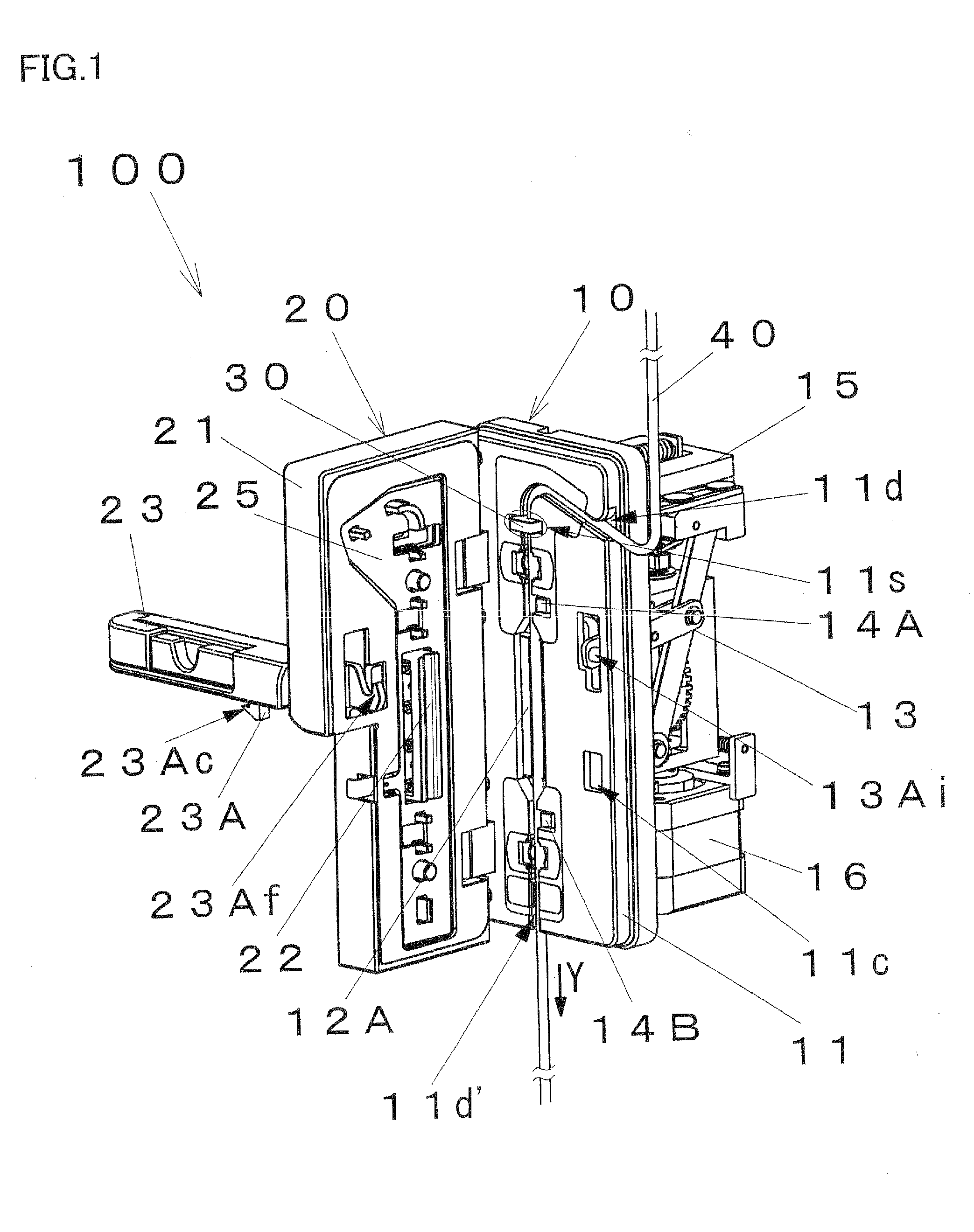
[0028]In a tube misload detection mechanism according to a first embodiment of the present invention, a door cannot be locked with a pump body in a closed state thereof when an infusion tube is not loaded at a correct position in the pump body, so that a misloaded state of the infusion tube can be detected.

[0029]More specifically, when the door is to be closed in a state that the infusion tube is not correctly loaded to a groove of the pump body, the infusion tube presses an inner door provided to the door, so that a force due to the pressing is transferred to a claw-shaped part that enables the door to be locked with the pump body. Therefore, the claw-shaped part is moved to a position where the door cannot be locked to be held in a stable state.

[0030]Hereinafter, structures and functions of a tube misload detection mechanism and an infusion pump using the tube misload detection mechanism according to the embodiment will be described in detail.

[0031][Infusion Pump]

[0032]FIG. 1 is a...

second embodiment

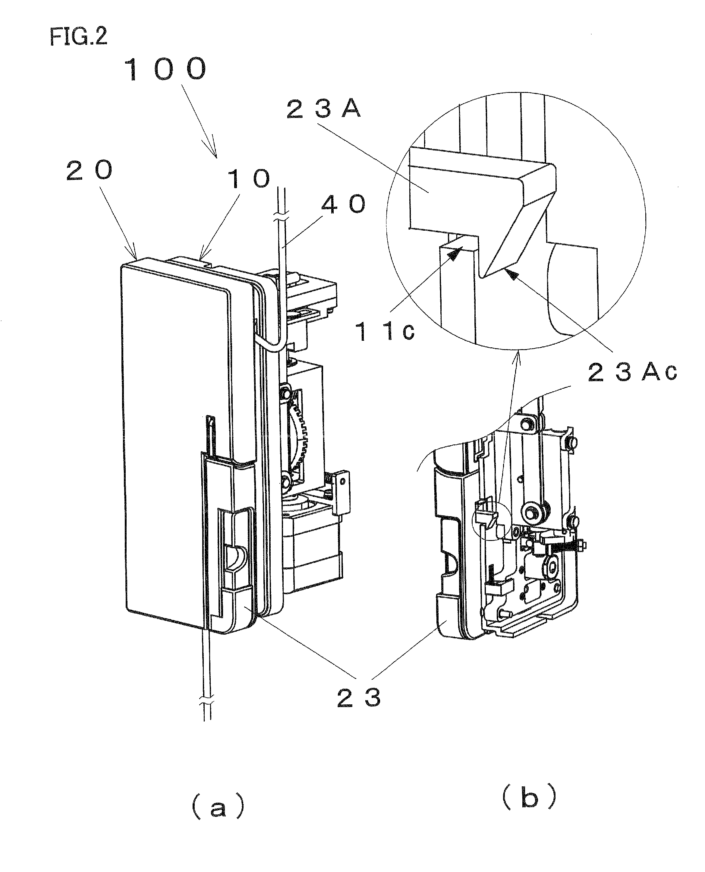
[0047]In a tube misload detection mechanism according to a second embodiment of the present invention, a protrusion portion for preventing manipulation of a handle in interlock with pressing of an inner door by the infusion tube when the infusion tube is not fitted at a correct position in a pump body is provided, so that a misloaded state of the infusion tube can be detected.

[0048]Hereinafter, a latching method of a door in an infusion pump using a structure of the tube misload detection mechanism according to the embodiment and detailed structure and function of the tube misload detection mechanism will be described.

[0049][Infusion Pump]

[0050]FIG. 4 is a perspective view illustrating an infusion pump 200 having the tube misload detection mechanism according to the second embodiment of the present invention. The infusion pump 200 is mainly constructed with a pump body 10 and a door unit 20 which is openably and closably provided to the pump body 10. In FIG. 4(a), the door unit 20 i...

third embodiment

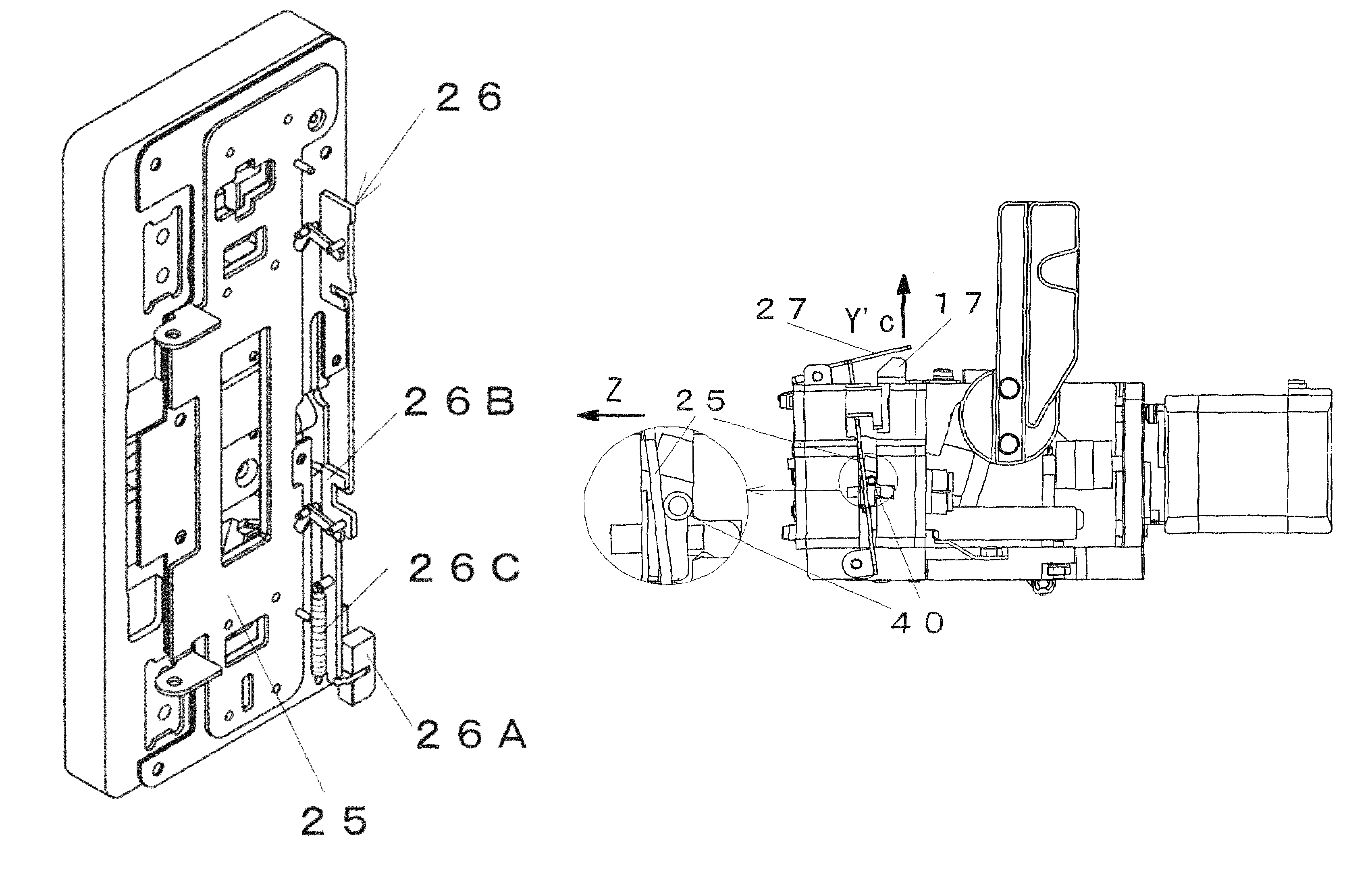
[0061]In a tube misload detection mechanism according to a third embodiment of the present invention, a position of a part of locking a door is moved in interlock with pressing of an inner door by an infusion tube when the infusion tube is not misloaded at a correct position in a pump body, so that the part of locking the door cannot be locked with the door. Therefore, a misloaded state of the infusion tube can be detected.

[0062]Hereinafter, a latching method of a door in an infusion pump using a structure of the tube misload detection mechanism according to the embodiment and structure and function of the tube misload detection mechanism will be described.

[0063]FIG. 7(a) is a perspective view illustrating an infusion pump 300 having the tube misload detection mechanism according to the third embodiment of the present invention. The infusion pump 300 is mainly constructed with a pump body 10 and a door unit 20 which is openably and closably provided to the pump body 10. In FIG. 7(a)...


PUM


Abstract

An infusion tube misloading detection mechanism for an infusion pump is provided at a low cost with a safety feature of detecting misloading of infusion tube. When a door unit is to be closed with respect to a pump body in a misloaded state of an infusion tube, a misload detection inner door is pressed by the misloaded infusion tube. Accordingly, an interlock part is prevented from being closed with the pump body. Therefore, the misloaded state can be easily identified.

Description

TECHNICAL FIELD[0001]The present invention relates to a system for preventing misload of an infusion tube in an infusion pump having a door which is used for a medical intravenous apparatus or the like.BACKGROUND ART[0002]Conventionally, a peristaltic infusion pump is mainly used as a medical infusion pump for feeding a medicinal solution or the like in an infusion tube, in which a door is openably and closably provided to an infusion pump body having a pump mechanism.[0003]The peristaltic infusion pump has a structure for performing feed, in which a plurality of fingers provided to a pump body perform reciprocating motion with individual phases to be in a peristaltic movement as a whole, so that infusion tubes disposed between the fingers and a receiving plate provided to the door are sequentially pressed toward a downstream so as to perform the feed. An example of the peristaltic infusion pump is disclosed in Patent Document 1.[0004]In such an infusion pump, if the infusion tube i...

Claims


Application Information

Patent Timeline
Patent Type & Authority Patents(United States)
IPC IPC(8): F04B43/08
CPCA61M5/14228F04B43/12F04B43/082A61M2205/14A61M2205/276
Inventor KASAI, TAKASHIHONDA, KENJI
Owner NAMIKI PRECISION JEWEL CO LTD
Why Eureka
Try Eureka