Connector

a technology of connecting rods and connectors, applied in the direction of coupling device details, coupling device connections, electric discharge lamps, etc., can solve the problems of difficult adjustment of the impedance of adjacent first contacts, increase of electrical resistance of conductors, and unfavorable transmission characteristics, etc., to achieve easy adjustment of impedance and improve relative permittivity , the effect of easy stabilization of the impedan

Inactive Publication Date: 2012-09-04
KYOCERA CONNECTOR PRODS CORP
View PDF16 Cites 50 Cited by
  • Summary
  • Abstract
  • Description
  • Claims
  • Application Information

AI Technical Summary

Benefits of technology

[0014]The present invention provides a connector having improved transmission characteristics while absorbing any positional deviation between the plug connector and the receptacle connector in two axial directions orthogonal to each other.
[0019]If the first contacts and the second contacts are made to have such structures, the first resiliently deformable portion and the second resiliently deformable portion can be made to be easily deformable.
[0024]Since the direction of absorption of the positional deviation of one of the plug connector and the receptacle connector is limited to one axial direction, the partition walls, which limit resilient deformation of the first resiliently deformable portions of the first contacts in one direction (being a major cause of fluctuations in impedance upon occurrence of positional deviation) and which are higher in relative permittivity than air (the relative permittivity thereof=1), can be installed in the first fixed insulator and the first movable insulator. Therefore, the impedance can be adjusted easily by, e.g., optimization (design change) of the spacing between each first contact and the adjacent partition wall and the shape of each partition wall; moreover, the impedance can be easily stabilized even when a positional deviation occurs between the plug connector and the receptacle connector.
[0025]Furthermore, since the first resiliently deformable portions of the first contacts only need to be resiliently deformed in one axial direction, it is possible to increase the cross sectional area of the first resiliently deformable portion of each first contact to be greater than that in a conventional structure in which a resiliently deformable portion of each contact is resiliently deformable in two axial directions. This makes it possible to achieve a reduction in electrical resistance of the conductor of each contact, thus making it possible to improve the transmission characteristics.

Problems solved by technology

However, if the aforementioned space that allows the resiliently deformable portion of each first contact to be resiliently deformed is formed on the first fixed insulator and the first movable insulator, no material exists between adjacent first contacts, so that the relative permittivity is fixed at 1, which makes it difficult to adjust the impedance of adjacent first contacts.
However, for instance, the electrical resistance of the conductor increases as the resiliently deformable portion is reduced in cross sectional area, which is unfavorable with respect to transmission characteristics.
For this reason, in the connector having the above described structure, it is difficult to improve the transmission characteristics of the set of first contacts.

Method used


Image

  • Connector
  • Connector
  • Connector

Examples


Embodiment Construction

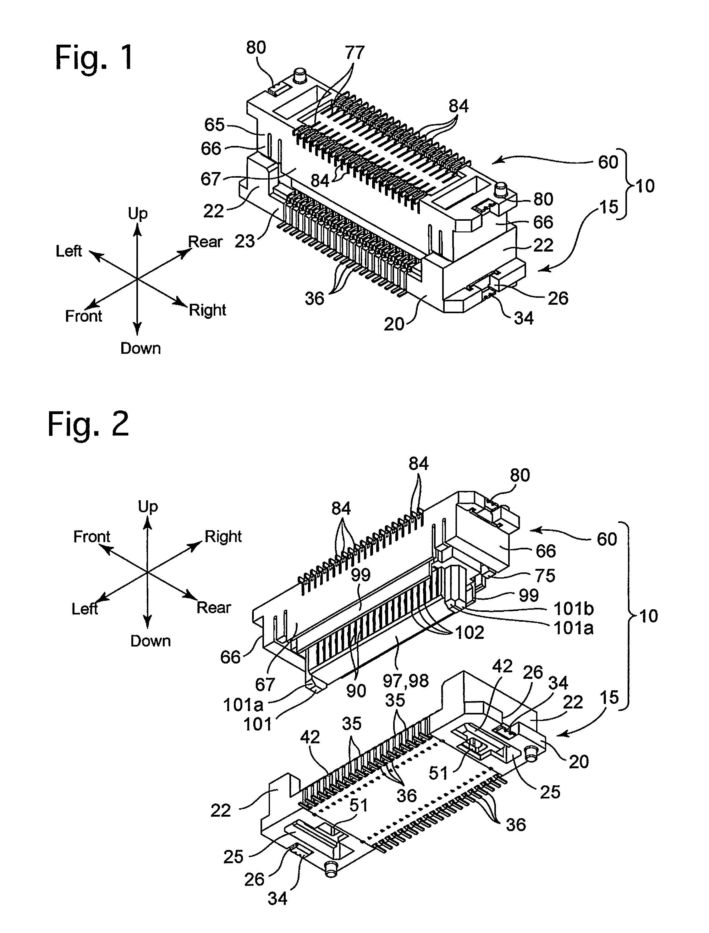
[0050]An embodiment of a connector according to the present invention will be hereinafter discussed with reference to FIGS. 1 through 22. In the following descriptions, forward and rearward directions, leftward and rightward directions, and upward and downward directions (vertical direction) of the connector 10 are determined with reference to the directions of the double-headed arrows shown in the drawings.

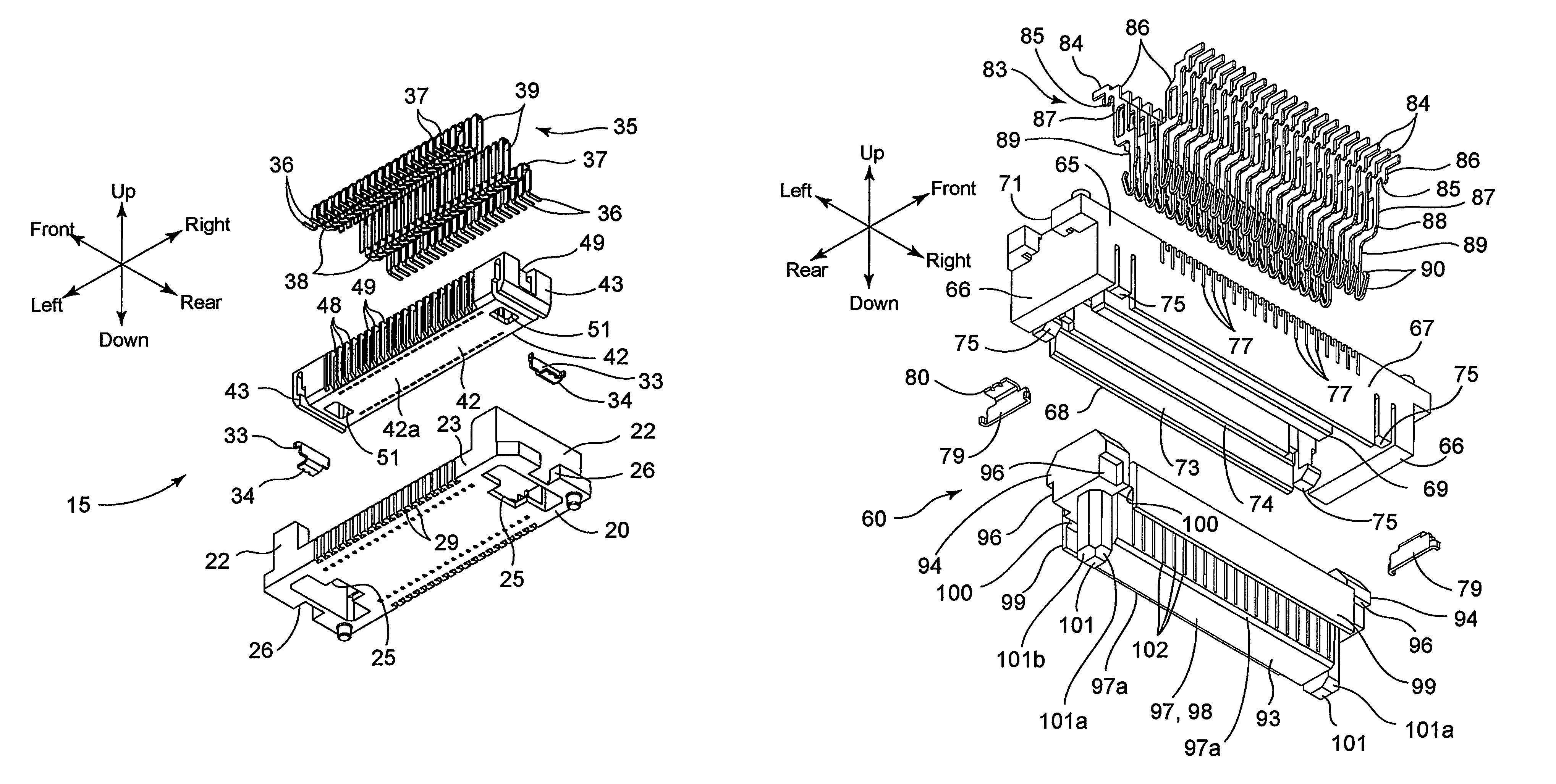
[0051]As shown in FIGS. 1 through 3, and 19 through 21, the connector 10 is provided with a plug connector (plug) 15 and a receptacle connector (receptacle) 60 which can be connected and disconnected to and from each other.

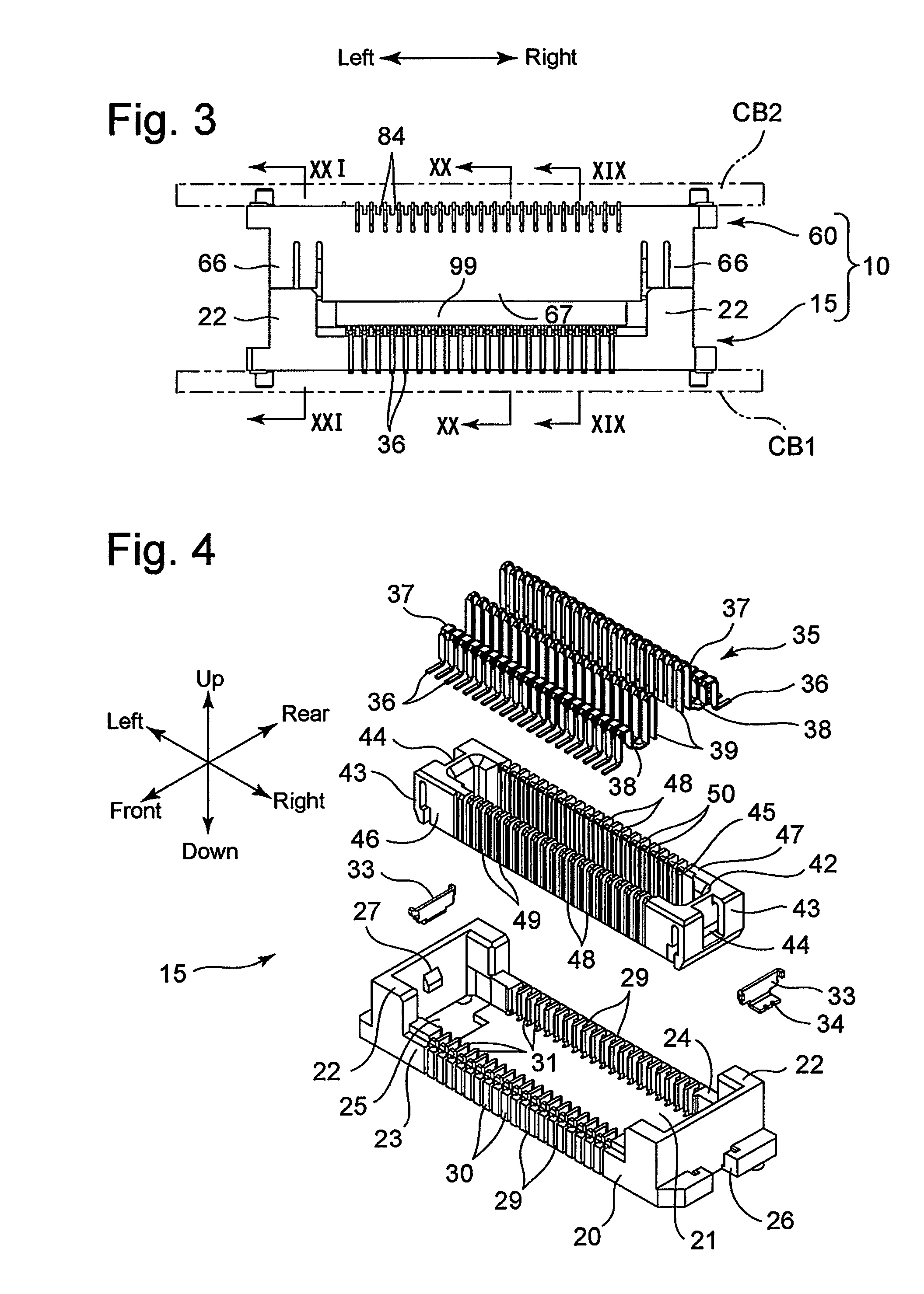
[0052]First, the detailed structure of the plug connector 15 will be hereinafter discussed with reference mainly to FIGS. 4 through 14.

[0053]The plug connector 15 is provided with a fixed insulator 20, a pair of (left and right) fixing fittings 33, a large number of plug contacts (first contacts / second contacts) 35 and a movable insulator 42 as relatively large...


PUM

PropertyMeasurementUnit
relative permittivityaaaaaaaaaa
thicknessaaaaaaaaaa

Abstract

A connector having a plug connector and a receptacle connector, one of which includes a first fixed insulator, first contacts aligned in a first direction orthogonal to a connecting / disconnecting direction and each including a first resiliently deformable portion deformable in a second direction orthogonal to the connecting / disconnecting direction and the first direction, a first movable insulator supported by the first contacts, and partition walls on the first fixed insulator and / or the first movable insulator. The other of the plug connector and the receptacle connector includes a second fixed insulator, second contacts aligned in the first direction, each including a second resiliently deformable portion deformable in the first direction and contactable with one first contact, and a second movable insulator supported by the second contacts and engaged with the first movable insulator when the first and second contacts come in contact with each other.

Description

CROSS REFERENCE TO RELATED APPLICATION[0001]The present invention is related to and claims priority of the following co-pending application, namely, Japanese Patent Application No. 2010-148694 filed on Jun. 30, 2010.BACKGROUND OF THE INVENTION[0002]1. Field of the Invention[0003]The present invention relates to a connector equipped with a plug connector and a receptacle connector which are capable of being connected and disconnected to and from each other. Even when the plug connector and the receptacle connector are brought into engagement with each other with some amount of positional deviation therebetween, the connector absorbs this positional deviation to thereby enable the plug connector and the receptacle connector to be electrically connected to each other with reliability.[0004]2. Description of the Prior Art[0005]This type of connector is usually called a “floating connector”, and conventional floating connectors are disclosed in, e.g., Japanese unexamined patent applicati...

Claims


Application Information

Patent Timeline
Patent Type & Authority Patents(United States)
IPC IPC(8): H01R12/00
CPCH01R12/716H01R13/6315H01R12/91Y10T29/49208H01R13/506
Inventor AKAI, NORIYUKITAKAHASHI, NAOKI
Owner KYOCERA CONNECTOR PRODS CORP
Why Eureka
Try Eureka