

Manufacturing device and manufacturing method of laminate
a manufacturing method and manufacturing device technology, applied in the direction of manufacturing tools, presses, chemistry apparatus and processes, etc., can solve the problems of high cost, high material cost and molding time, and difficult three-dimensional molding of complex shapes, and achieve excellent handling properties and formability.
- Summary
- Abstract
- Description
- Claims
- Application Information
AI Technical Summary
Benefits of technology
Problems solved by technology
Method used
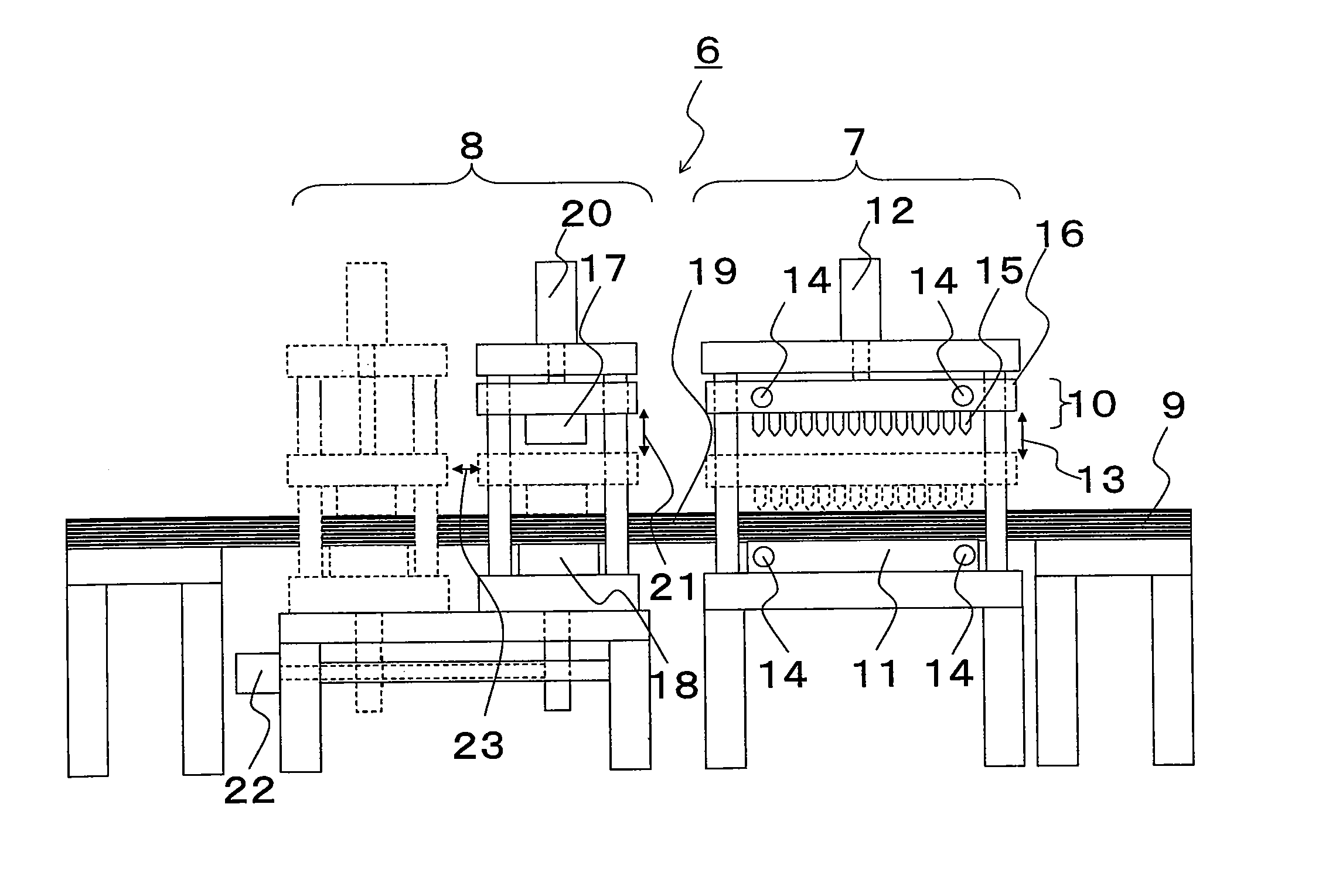
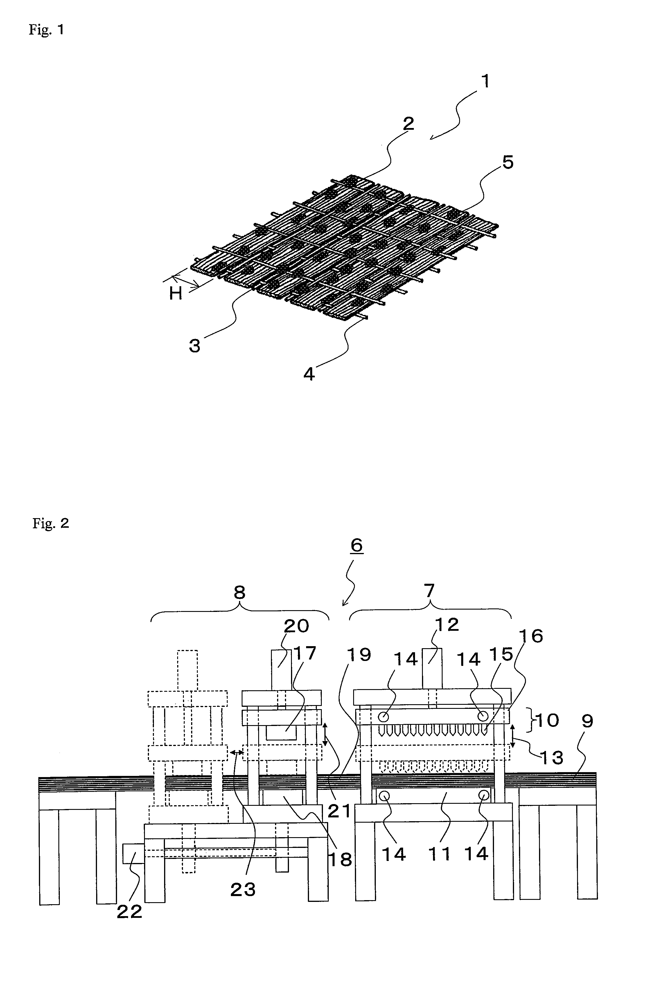
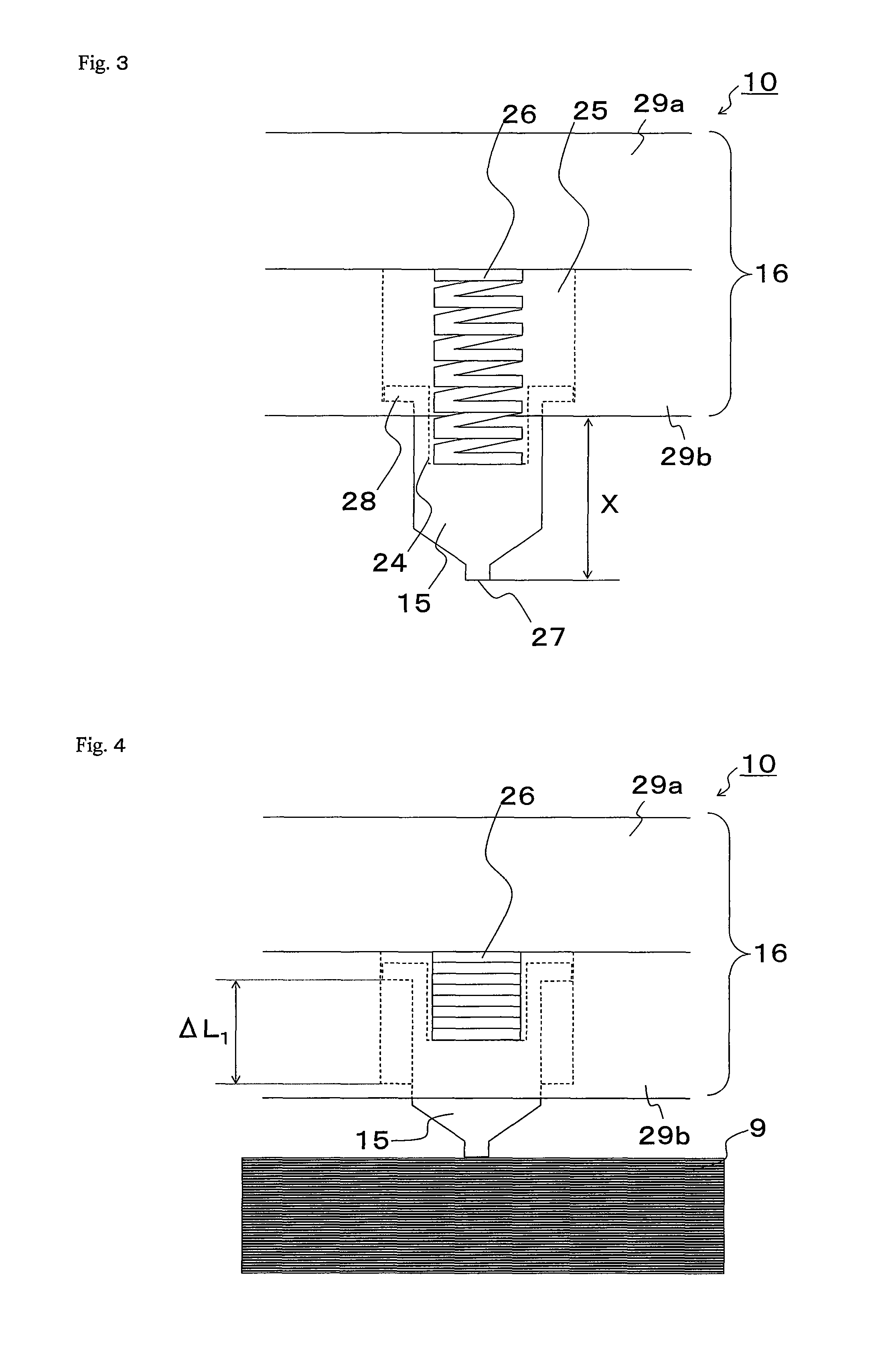
Image

Examples
example 1
[0104]With carbon fiber yarn (reinforcing fiber bundle) in which the number of filaments is 24,000, the width is 5.4 mm, the tensile strength is 5.8 GPa, and the tensile modulus is 290 GPa as the warp, and using a covering filament covered (coated) with nylon 66 filament thread of 17 dtex in which refining process is performed on the glass fiber thread attached with coupling agent of 22.5 dtex as the auxiliary thread of the warp and the nylon 66 filament thread of 17 dtex performed with refining process as the auxiliary thread of the weft, the uni-directional non-crimp carbon fiber fabric having the carbon fiber areal weight of 190 g / cm2 was manufactured.
[0105]The particles having an average particle diameter of 120 μm and containing thermoplastic resin having a glass transition temperature of 70° C. were evenly dispersed on both sides of the uni-directional non-crimp carbon fiber fabric as adhesive resin with 13 g / m2 per one side, and heated to 200° C. to be attached to the surface...
example 2
[0128]The carbon fiber base material same as example 1 was cut to obtain the reinforcing fiber base material in which the carbon fiber yarn is aligned in the 45° direction, 0° direction, −45° direction, and 90° direction with respect to the longitudinal direction of the base material, and such reinforcing fiber base materials were sequentially laminated such that the alignment direction of the carbon fiber yarn was 45° / 0° / −45° / 90° / 90° / −45° / 0° / 45° to thereby prepare the laminate precursor. The eight reinforcing fiber base materials sequentially laminated such that the alignment direction of the carbon fiber yarn was 45° / 0° / −45° / 90° / 90° / −45° / 0° / 45° all have an equal width of 0.55 mm, and a length of 6.00 m, 5.99 m, 5.98 m, 5.97 m, 5.96 m, 5.95 m, 5.94 m, and 5.93 m. All the reinforcing fiber base materials were laminated with one end in the longitudinal direction thereof aligned. As a result, a slope shape 33 (called ply drop) formed at one end of the laminate precursor, as shown in t...
PUM
| Property | Measurement | Unit |
|---|---|---|
| glass transition temperature Tg | aaaaa | aaaaa |
| glass transition temperature Tg | aaaaa | aaaaa |
| pressure | aaaaa | aaaaa |
Abstract
Description
Claims
Application Information