Motor with stator configuration for increased coil length and coil space factors

a technology of stators and motors, applied in the direction of windings, magnetic circuit rotating parts, magnetic circuit shapes/forms/construction, etc., can solve the problems of affecting production efficiency, time required for coil winding operation, and complicated method of winding coils, so as to reduce the deformation amount in the coil end portion of the coil, prevent damage to the coating of the lead line forming, and increase the distance between adjacent slot portions

Inactive Publication Date: 2012-09-04
HONDA MOTOR CO LTD
View PDF30 Cites 3 Cited by
  • Summary
  • Abstract
  • Description
  • Claims
  • Application Information

AI Technical Summary

Benefits of technology

[0015]The present invention is proposed in light of the above matters and provides a motor that enables an overall coil length to be shortened and which improves the space factor of the coils. Furthermore, the present invention provides a motor that enables a reduction in an amount of coil deformation.
[0016]In order to improve the space factor of the coil in the slot portion, improve the efficiency of the coil winding operation, and downsize the motor, the present inventors conducted diligent research for a method of manufacturing a stator by using the method disclosed in Japanese Unexamined Patent Application, First Publication No. 2002-44893 in a state in which the stator core pieces are arranged in a band shape to thereby wind the coils as shown in FIG. 38, and thereafter arrange the plurality of stator core pieces in a cylindrical shape.

Problems solved by technology

Thus, the method of winding the coils is more complicated, time is required for the coil winding operation and production efficiency is adversely affected.
However, when the method disclosed in Japanese Unexamined Patent Application, First Publication No. 2002-44893 is used to wind coils and thereafter a stator is manufactured by arranging a plurality of stator core pieces into a cylindrical shape, there is the problem in that the resistance produced in the coil increases and motor performance is adversely affected.
Furthermore, there is the problem in that the insulation characteristics of the coil are reduced.

Method used


Image

  • Motor with stator configuration for increased coil length and coil space factors
  • Motor with stator configuration for increased coil length and coil space factors
  • Motor with stator configuration for increased coil length and coil space factors

Examples


first embodiment

[0101]The preferred embodiments of the present invention will be described below with reference to FIGS. 1 to 16.

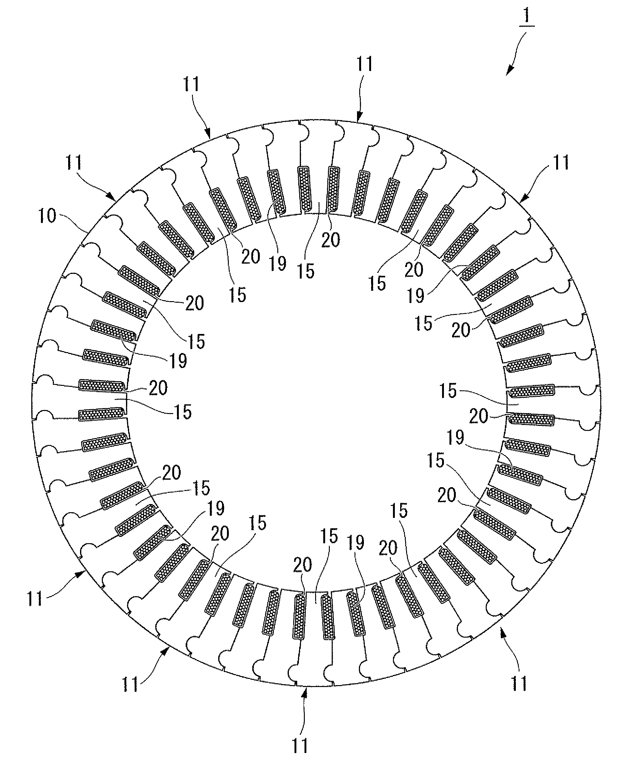
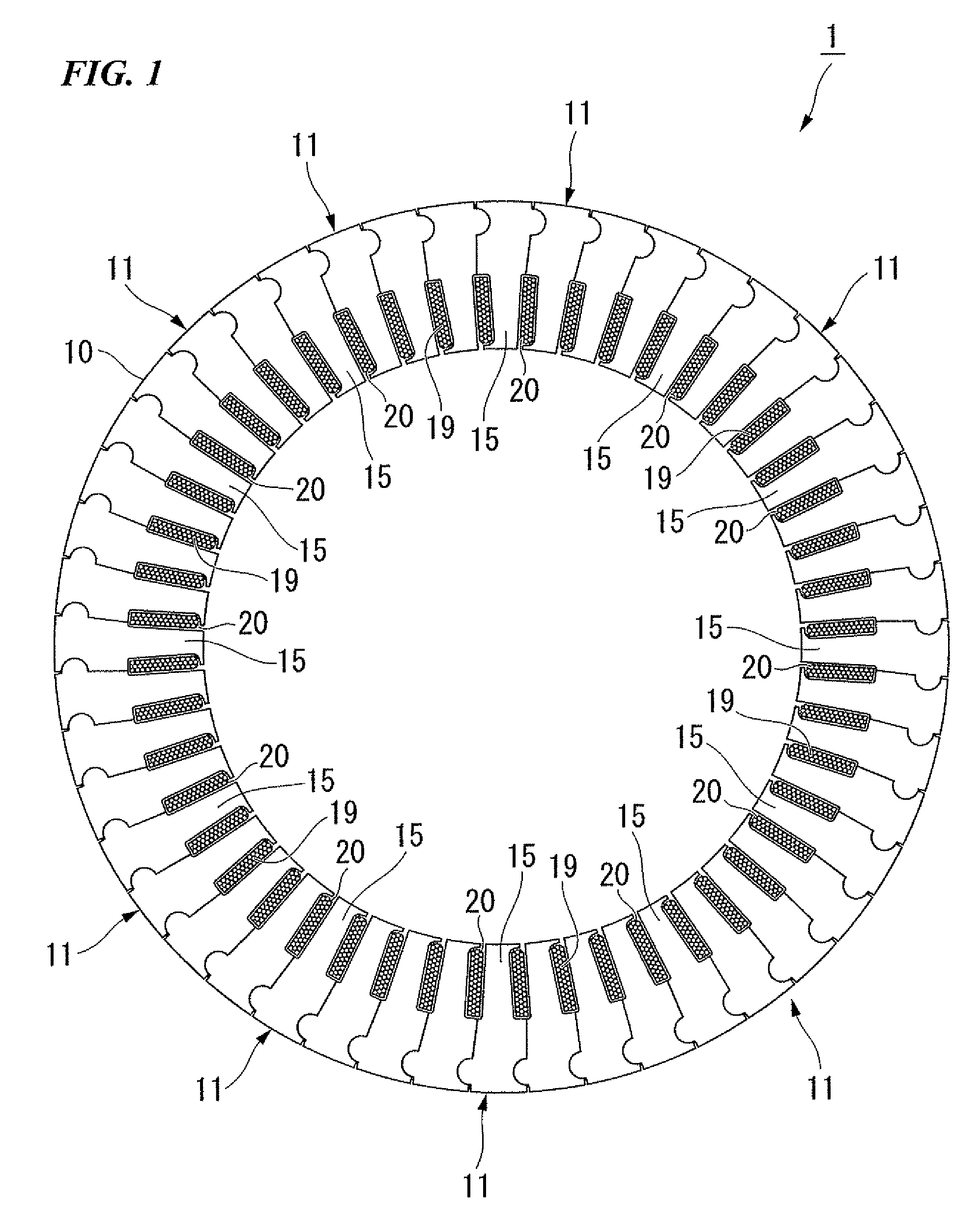
[0102]FIG. 1 is a plan view of a stator.

[0103]In FIG. 1, a coil 20 is shown in cross section from an upper end of a stator core 10. As shown in FIG. 1, the stator 1 includes the stator core 10 formed in a cylindrical shape, a plurality of teeth 15 (teeth portions) adjacent to the stator core 10, slots 19 (slot portions) formed between the teeth 15 and 15, and coils 20 disposed on the slots 19.

[0104]A rotor (not shown) is rotatably disposed in a space formed in the center of the cylindrical stator 1.

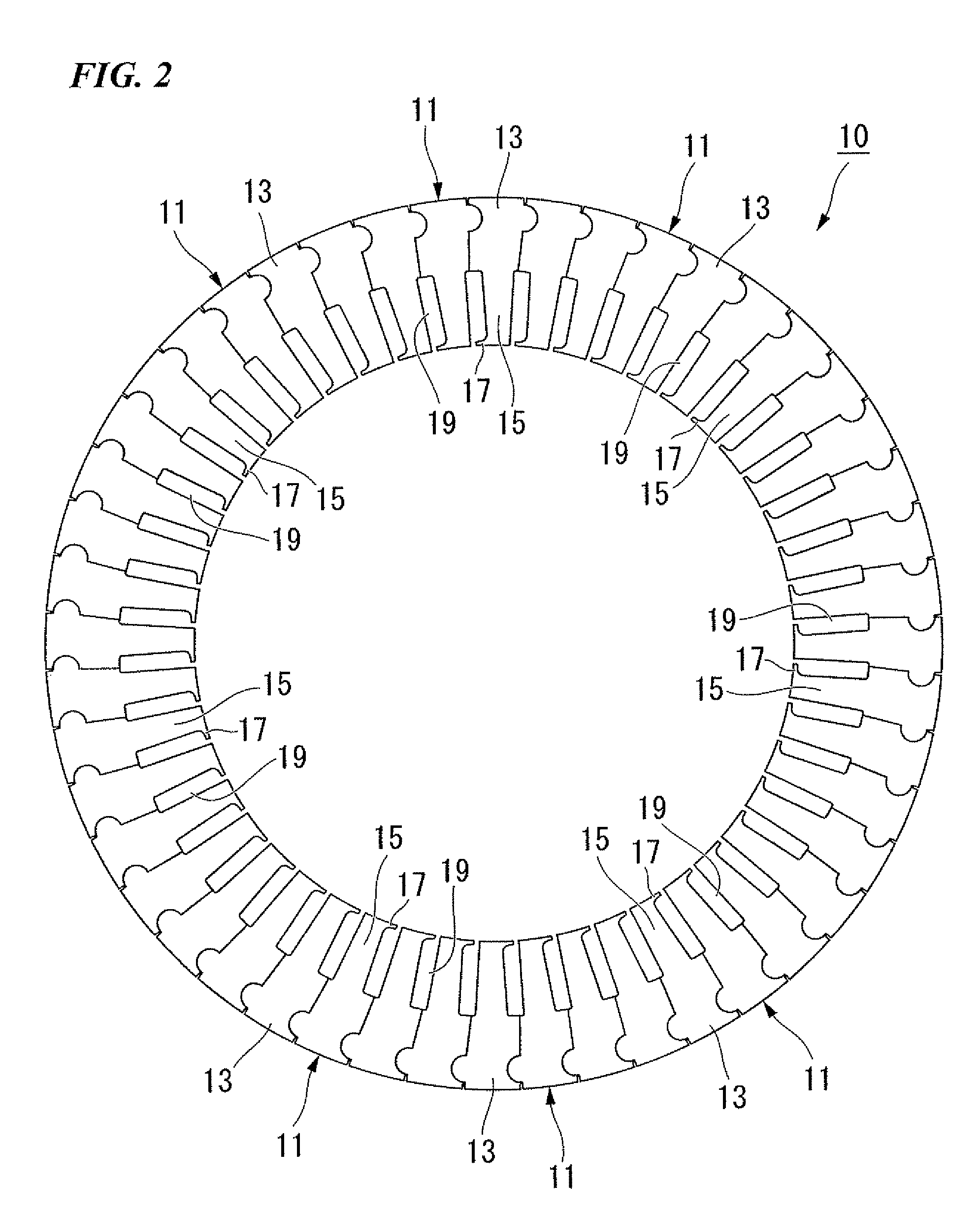
[0105]FIG. 2 is a plan view of a stator core.

[0106]As shown in FIG. 2, the stator core 10 is configured by connecting a plurality of core pieces 11 (stator core pieces) in a cylindrical shape. The stator core 10 includes a yoke 13 (yoke portion) configuring an outer-peripheral of the cylinder, teeth 15 that protrude from the yoke 13 towards the center of the cylinder, and a dis...

second embodiment

[0171]Next, a second embodiment of the present invention will be described making reference to FIGS. 17 to 19.

[0172]The second embodiment differs from the first embodiment only with respect to the configuration of the core piece, and other configurations are substantially similar to the first embodiment. As a result, the same reference numerals denote the same members and detailed description will not be repeated.

[0173]FIG. 17 is a plan view of a core piece 70.

[0174]As shown in FIG. 17, the core piece 70 is configured by laminating a plurality of flat steel plates 51 that form the yoke 13, the teeth 15, and the distal end portion 17. One tooth 15 is formed on one core piece 70. That is, a core piece 70 is divided on each tooth 15. The flat steel plates 71 configuring the core piece 70 can be simply manufactured by press forming.

[0175]In the second embodiment, a claw portion 72 is formed only the side portion of the two side portions that form the distal end portion 17 of the teeth 1...

third embodiment

[0188]The preferred embodiments of the present invention will be described below with reference to FIGS. 20 to 37.

[0189]FIG. 20 is a plan view of a stator.

[0190]In FIG. 20, a coil 120 is shown in cross section from an upper end of a stator core 110. As shown in FIG. 20, the stator 101 includes the stator core 110 formed in a cylindrical shape, a plurality of teeth 115 (teeth portions) adjacent to the stator core 110, slots 119 (slot portions) formed between the teeth 115 and 115, and coils 120 disposed on the slots 119.

[0191]A rotor (not shown) is rotatably disposed in a space formed in the center of the cylindrical stator 101.

[0192]FIG. 21 is a plan view of a stator core.

[0193]As shown in FIG. 21, the stator core 110 is configured by connecting a plurality of core pieces 111 (stator core pieces) in a cylindrical shape. The stator core 110 includes a yoke 113 (yoke portion) configuring an outer-peripheral of the cylinder, teeth 115 that protrude from the yoke 113 towards the center ...


PUM


Abstract

A motor including a stator and rotor. The stator includes a stator core, slot portions and coils. The stator core includes stator core pieces with teeth portion having a distal end portion and two side portions, a yoke portion, and a claw portion formed at one of the two side portions. At the distal end portion, the stator core pieces are connected so that claw portions protrude in the same circumferential direction to form the stator core into a cylindrical shape. The slot portions are formed between adjacent teeth portions and between the stator core pieces. The coils form three phases which are inserted into the slot portions, are bridged between two of the slot portions and include end portions that protrude from an edge face of the stator core in an axial direction. The coils are arranged so that the end portions are intersected with each other.

Description

BACKGROUND OF THE PRESENT INVENTION[0001]1. Field of the Present Invention[0002]The present invention relates to a motor.[0003]This application claims priority from Japanese Patent Application No. 2009-122966, filed on May 21, 2009, and Japanese Patent Application No. 2009-143154, filed on Jun. 16, 2009, the contents of which are incorporated herein by reference.[0004]2. Description of Related Art[0005]Conventionally, an inner rotor type of motor is known. An inner rotor motor includes a cylindrical stator and a rotor (rotating element).[0006]An inner rotor motor disposes a rotor in a space formed on an inner side of a stator to thereby enable rotation of the rotor with respect to the stator.[0007]Furthermore, coils are wound in a slot portion formed between teeth portions adjacent to the stator. Methods including distributed winding or concentrated winding are known. as manufacturing methods for winding coils.[0008]Generally, a configuration in which coils are wound using distribut...

Claims


Application Information

Patent Timeline
Patent Type & Authority Patents(United States)
IPC IPC(8): H02K1/06H02K3/00
CPCH02K1/148H02K1/16H02K3/28H02K15/066
Inventor SHIKATA, SATOSHI
Owner HONDA MOTOR CO LTD
Why Eureka
Try Eureka