Clock integrated circuit

a clock and integrated circuit technology, applied in the direction of generating/distributing signals, pulse techniques, instruments, etc., can solve the problems of consuming a lot of die space, relative complexity of buffer circuits, and increasing costs

Active Publication Date: 2012-09-04
MACRONIX INT CO LTD
View PDF5 Cites 11 Cited by
  • Summary
  • Abstract
  • Description
  • Claims
  • Application Information

AI Technical Summary

Problems solved by technology

These relatively complicated buffer circuits devote significantly more die area, and cost, to isolating such power fluctuations from the clock circuit.

Method used


Image

  • Clock integrated circuit
  • Clock integrated circuit
  • Clock integrated circuit

Examples


Embodiment Construction

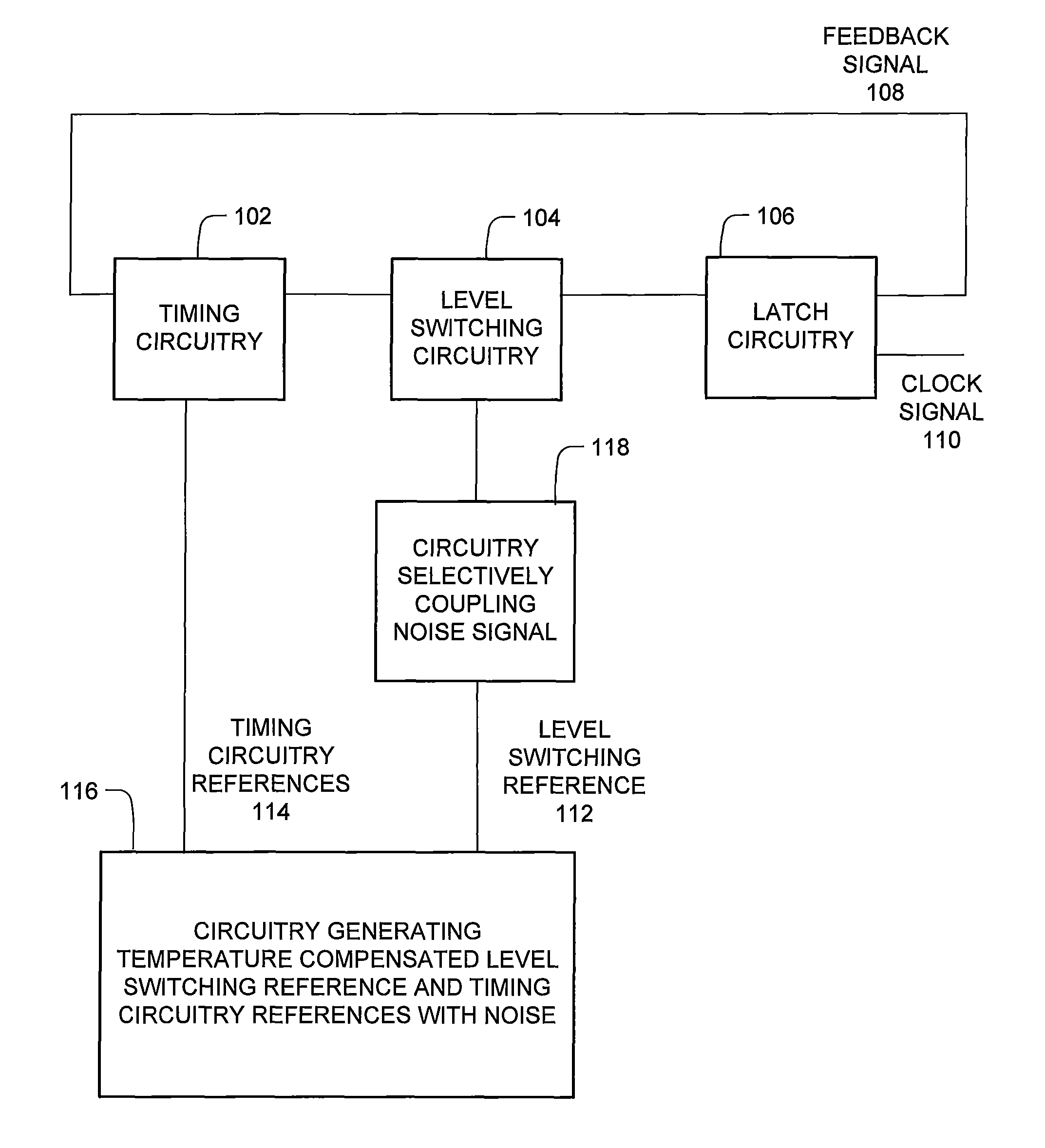
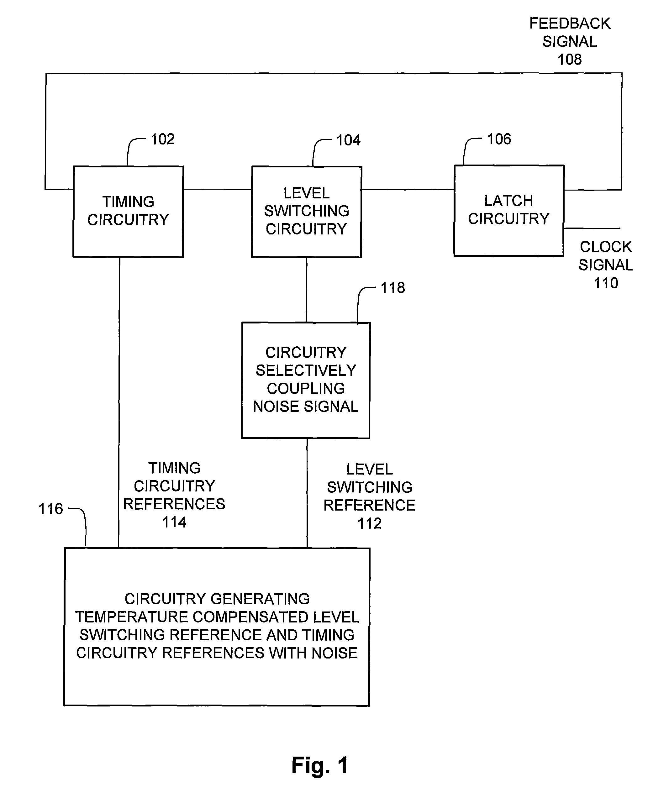
[0074]FIG. 1 is a block diagram of an integrated clock circuit with tolerance to variations such as temperature, ground voltage, and power voltage.

[0075]The clock integrated circuit generally has a loop structure, with timing circuitry 102, level switching circuitry 104, and latch circuitry 106. The latch circuitry 106 generates a feedback signal from latch circuitry 106 back to timing circuitry 102, and the clock signal output 110. The timing circuitry 102 alternates between two reference signals according to a time constant. The time constant accordingly determines the timing of the clock integrated circuit. A typical example of the time constant is an exponential time constant that characterizes the rise and fall of an RC circuit or an RL circuit. The level switching circuitry monitors the output of the timing circuitry 102, and changes the output depending on whether the timing circuitry 102 is sufficiently high, or low. Examples of latch circuitry 106 are an SR latch, SR NAND l...


PUM


Abstract

The clock circuit of an integrated circuit operates with variations such as temperature, ground noise, and power noise. Various aspects of an improved clock integrated circuit address one or more of the variations in temperature, ground noise, and power noise.

Description

BACKGROUND[0001]1. Field of the Invention[0002]The present technology relates to an integrated circuit with a clock circuit, tolerant to variations such as temperature, ground noise, and power noise.[0003]2. Description of Related Art[0004]The clock circuit of an integrated circuit operates with variations such as temperature, ground noise, and power noise. Because these variations affect the final timing of the output clock signal, various approaches address the variations in order to generate a uniform output clock signal despite the variations.[0005]For example, U.S. Pat. No. 7,142,005 by Gaboury seeks to decouple power fluctuations from the clock signal, by adding buffer circuits with active loads, independent bias circuitry, and bias circuitry. These relatively complicated buffer circuits devote significantly more die area, and cost, to isolating such power fluctuations from the clock circuit.[0006]What is needed is an approach to address such variations with reduced complexity...

Claims


Application Information

Patent Timeline
Patent Type & Authority Patents(United States)
IPC IPC(8): G06F1/12G06F1/00G06F1/04H03B5/32
CPCG06F1/04G06F1/08G06F1/12H03K19/0175H03L5/00G05F3/02G06F1/10H03K19/018528
Inventor CHEN, CHUNG-KUANGHUNG, CHUN-HSIUNGCHEN, HAN-SUNG
Owner MACRONIX INT CO LTD
Why Eureka
Try Eureka