
Ball valve

a ball valve and valve body technology, applied in the direction of valve details, valve housings, valve arrangements, etc., can solve the problems of exacerbated possibility of disadvantageous outcome, ball to start rotating toward the open position, and disadvantages in the prior art, and achieve greater flexibility and the effect of coping ability

Active Publication Date: 2012-09-11
KING ROBERT W
View PDF6 Cites 3 Cited by
  • Summary
  • Abstract
  • Description
  • Claims
  • Application Information

AI Technical Summary

Benefits of technology

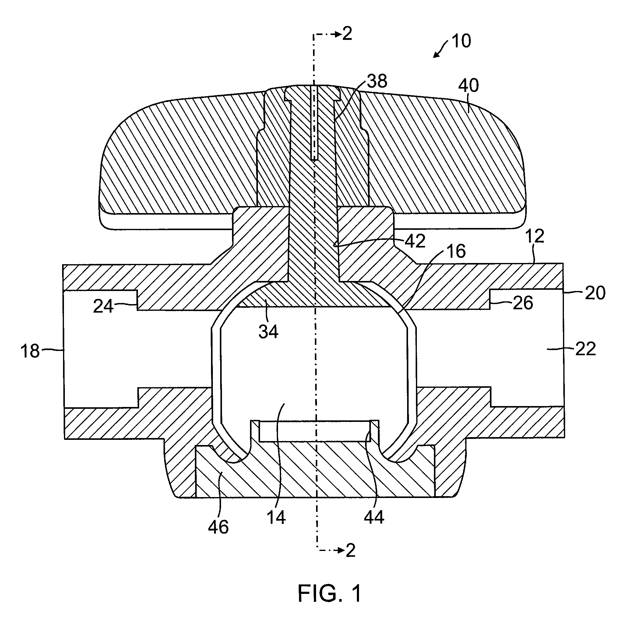
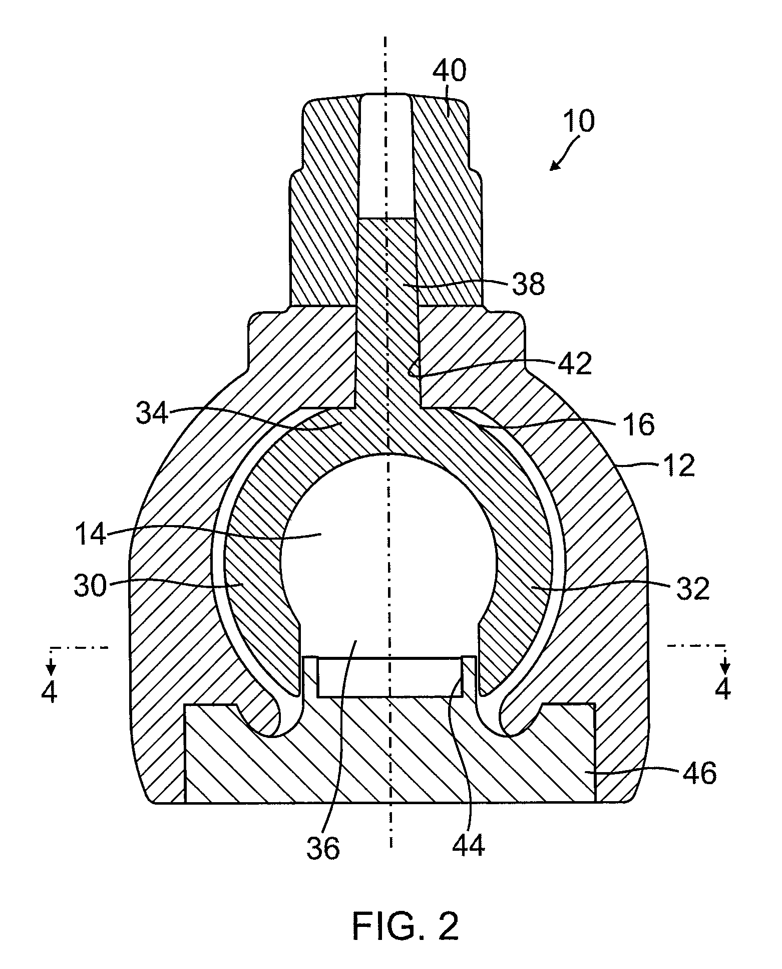
[0007]The cam element is shaped so that, when the ball is rotated from the open condition to the closed condition, the cam element forces the arms through three distances of separation from each other, namely: a first distance of separation in which the arms are spaced a first distance from each other, when the ball has undergone no rotation from the fully open condition; a second distance of separation in which the arms are spaced a second distance from each other, when the ball has undergone some rotation from the fully open condition towards the closed condition but has not reached the closed condition; and, a third distance of separation in which the arms are spaced a third distance from each other, and in which the ball has undergone rotation to the closed condition. The third distance is greater than the first distance, and the second distance is greater than the third distance. Under this configuration, force or torque required to move the ball from the open condition to the closed condition reduces over the last few degrees of rotation towards the closed condition. By corollary, the force required to move the ball from the closed condition towards the open condition requires an increasing force for the first few degrees of rotation. Preferably, the angle of rotation over which such an increasing force occurs is between about 10 and 20 degrees, and most preferably about 15 degrees. This feature has the advantageous effect of tending to prevent the ball from accidentally opening from the closed condition. Preferably, the difference between the second distance and the third distance is not less than 15% of the difference between the second distance and the first distance.
[0010]In this facet of the invention, the cam element is further shaped to include a hollowed out portion with a wall acting as a cantilevered section that is in contact with the arms as the ball rotates. This feature allows the cam element wall to bend inwardly under force from the arms, and provides the ball valve with greater ability to cope with salt and sediment that may be deposited on the ball, in the valve throughbore and chamber. In a preferred aspect, the cantilevered section has an aspect ratio of more than three, and further preferred, the cantilevered section has a length of more than three millimeters. In another aspect, the cantilevered section has at least one discontinuity along the perimeter of the cam element. This provides even greater flexibility to the interface between the arms and the cam element.

Problems solved by technology

However, disadvantages are found to exist in the prior art.
First, it has been found that water pressure in the conduit line is capable of cracking the seal between the ball and the chamber, causing the ball to start rotating toward the open position.
The possibility of this disadvantageous outcome may be exacerbated if a vibration is imposed on the closed valve, which would tend to reduce the frictional resistance that otherwise restrains the ball from moving away from its closed position.
Second, it has been found that the presence of salt or sediment deposits in the valve housing and / or on the ball surface may tend to obstruct the ball from reaching its fully closed position.

Method used


Image

  • Ball valve
  • Ball valve
  • Ball valve

Examples


Embodiment Construction

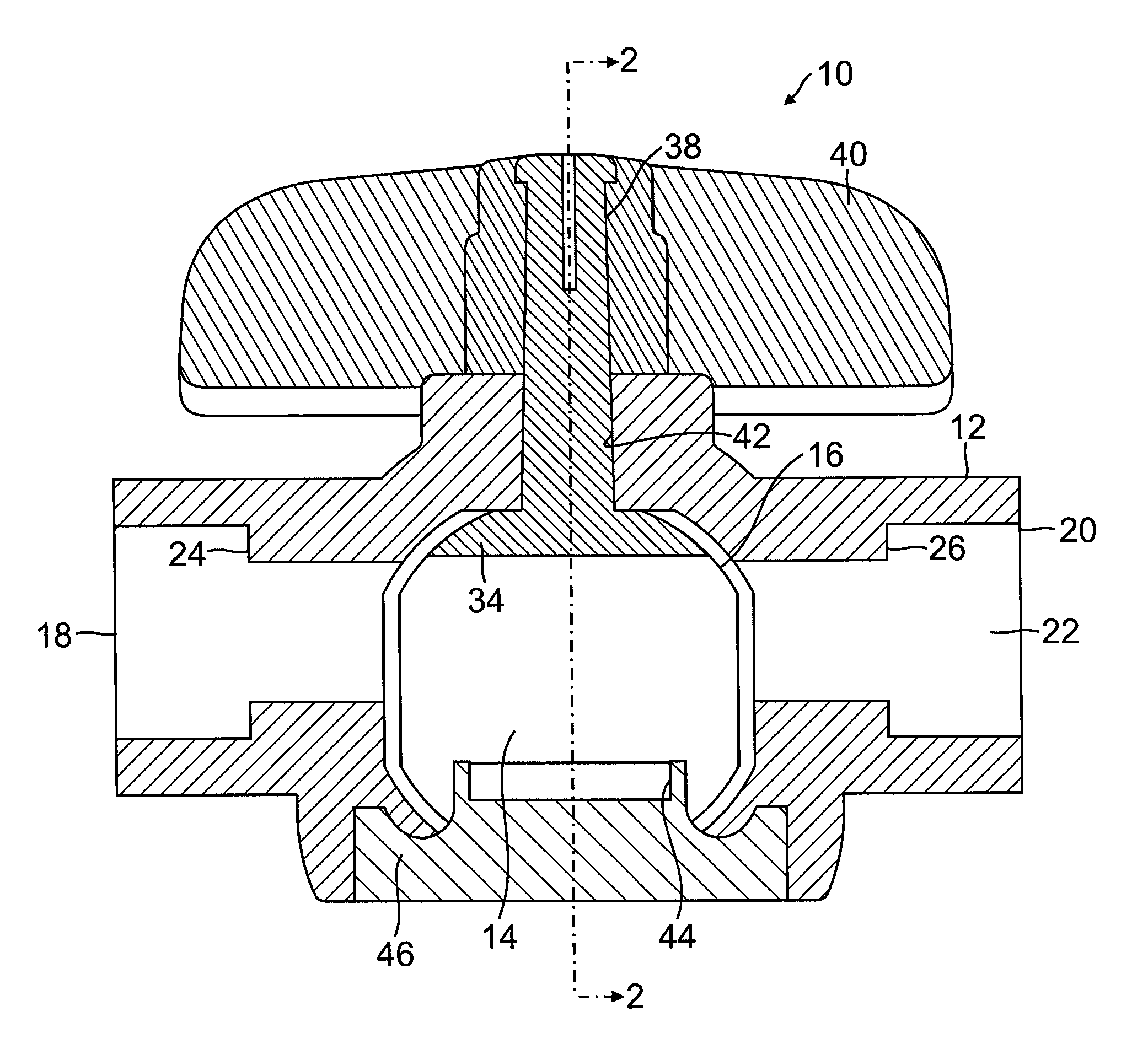
[0024]With reference to the drawings, which are provided for exemplification and not limitation, there is described a ball valve having features of the present invention. With reference to FIGS. 1 and 2 of the drawings, a ball valve 10 is shown having a valve housing 12. The housing 12 defines a central chamber 14 configured to have an inner profile that is spherical to receive a rotatable ball 16 as will be described. Rotatable ball 16 is preferably made of a suitable resilient material, such as Acetal. The remaining components of the invention may be of any suitable material. In various embodiments, the components may be made from Acetal, acrylonitrile butadaiene styrene (ABS), polyvinyl chloride (PVC), or chlorinated polyvinyl chloride (CPVC).

[0025]The housing 12 further defines an inlet port 18 and an outlet port 20. A throughbore 22 extends between the inlet port and the outlet port, and passes through the chamber 14 to provide a passageway for fluid to flow through the valve 1...


PUM


Abstract

A ball valve having a cam element, and a ball having a left arm and a right arm with a slot between each arm. A terminal portion of each arm is positioned adjacent the cam element. The cam element is shaped so that, when the ball is rotated from the open condition to the closed condition, the cam element forces the arms through three distances of separation. A first distance, when the ball has undergone no rotation from the fully open condition. A second distance, when the ball has undergone some rotation from the fully open condition towards the closed condition but has not reached the closed condition. A third distance in which the ball has undergone rotation to the closed condition. The third distance is greater than the first distance, and the second distance is greater than the third distance.

Description

BACKGROUND[0001]The present invention relates to valves for regulating fluid flow.[0002]Ball valves are known in the art, and have traditionally been used as an effective mechanism for regulating fluid flow in conduits. They are commonly found in plumbing for the home, recreational vehicles, mobile homes, garden, or general landscaping. Various structural arrangements have been achieved for interrupting fluid flow by twisting a handle of a ball valve, and resuming fluid flow by twisting the handle back again. Typically, ball valves include a housing having an inlet port and an outlet port. A throughbore internally connects the inlet port to the outlet port. An inlet conduit and an outlet conduit may be connected to the inlet port and the outlet port respectively. A central chamber is positioned in the path of the throughbore. A ball with a throughbore is positioned within the central chamber. The ball may be rotated by an external handle. When the handle is twisted to align the thro...

Claims


Application Information

Patent Timeline
Patent Type & Authority Patents(United States)
IPC IPC(8): F16K25/00
CPCF16K5/0647F16K5/20F16K27/067
Inventor KING, ROBERT W.
Owner KING ROBERT W
Learn More