Exhaust air dryer with heat exchanger

a technology of exhaust air dryer and heat recovery, which is applied in drying machines, lighting and heating apparatus, and cleaning using liquids, etc., can solve the problems of reducing the airflow volume, deteriorating the performance figures and energy consumption, and exhaust air dryers with heat recovery have failed to establish themselves in the marketplace, so as to reduce the pressure loss

Active Publication Date: 2012-09-18
BOSCH SIEMENS HAUSGERATE GMBH
View PDF11 Cites 32 Cited by
  • Summary
  • Abstract
  • Description
  • Claims
  • Application Information

AI Technical Summary

Benefits of technology

[0009]It is an object of the present invention to specify an exhaust air dryer of the type defined at the outset, in which the possibility is created of restricting or even eliminating a deterioration of efficiency as a result of soiling of the heat exchanger, where both soiling by fluff in the exhaust air dryer and soiling by dust and the like from the environs of the exhaust air dryer are taken into account.
[0011]By means of the flushing device, the associated inflow surface or inflow surfaces can be cleaned, whereby adhering soiling (fluff, suspended particles etc.) is removed. A deterioration in efficiency as a result of any soiling by fluff, dust or the like is thereby sharply reduced or even eliminated. Given the presence of a flushing device, a filter and its regular maintenance can if appropriate be dispensed with, which enhances the user-friendliness of the exhaust air dryer.
[0015]In one embodiment of the inventive exhaust air dryer, the air ducts comprise a supply air duct to feed process air to the first inflow surface and a heat sink inlet channel to feed process air to the second inflow surface, between which is arranged a through-opening which can be sealed by means of a flap, where the shared flushing device is arranged on one side of the through-opening and is set up, when the through-opening is open, to flush both inflow surfaces. The activated flushing device thus also flushes the inflow surface located on the other side of the through-opening through the open through-opening. In the case of a non-activated flushing device, the flap and thus the through-opening are closed, in order to prevent an exchange of air between the air ducts during drying operation, and thus a reduction of the efficiency of the heat pump.
[0018]To prevent residual flushing liquid collecting, an edge of the through-opening preferably directly abuts or extends almost to the inflow surfaces. For thorough cleaning, the width of the through-opening preferably extends generally at least across the width of the inflow surfaces.
[0023]If the upper inflow surface is the inflow surface of the heat source and the lower inflow surface is the inflow surface of the heat sink, as the heat source is generally arranged on the inlet side and the heat sink generally on the pressure side of the process air fan, a pressure drop applies at the flap, which presses this upwards. Where the flap is pressed from below onto the flushing liquid through-opening, the spring dimension then only needs to be sufficiently large that the flap with the pressure drop presses on the through-opening. In an extreme case, the flap is held against the opening solely by the pressure drop in opening mode operation; the flap then serves only to ensure the closure at the beginning of the drying process. In the case of non-activated drying, the flap is able to hang down; this improves flushing liquid throughput, but may possibly not guarantee closure of the flap in drying mode operation. The spring element can further be embodied such that the flap opens during a flushing process under the weight of the flushing liquid against the force exerted by the spring element, so that water can flow downwards. To this end the spring is designed to be sufficiently weak to avoid the accumulation of flushing liquid on the flap during the flushing process and flushing liquid residues after the flushing process.
[0029]To reduce pressure losses in particular at the heat source, the process air fan can preferably be arranged before the drying chamber in the direction of flow (“pressure-exerting system”).

Problems solved by technology

In the case of a known condensation dryer with a heat pump, its heat sink is connected from the airflow perspective such that by far the majority of the dirt particles (fluff etc.) suspended in the process air is deposited thereupon, which leads to a reduction in the airflow volume and thus to a deterioration in the performance figures and energy consumption.
To date, exhaust air dryers with heat recovery have failed to establish themselves in the marketplace; exhaust air dryers are appreciated primarily as simple, low-cost dryers, which require very little maintenance; in the case of an exhaust air dryer with heat recovery however, both an increased price attributable to the heat exchanger or the heat pump and greater maintenance effort as a result of the need to dispose of the condensate occurring and any possible fluff accumulating can be expected.
A further, hitherto little appreciated problem also applies: an exhaust air dryer takes the process air needed for a drying process from its surroundings, and guides it across the items to be dried just once in an open circuit.

Method used


Image

  • Exhaust air dryer with heat exchanger
  • Exhaust air dryer with heat exchanger
  • Exhaust air dryer with heat exchanger

Examples


Embodiment Construction

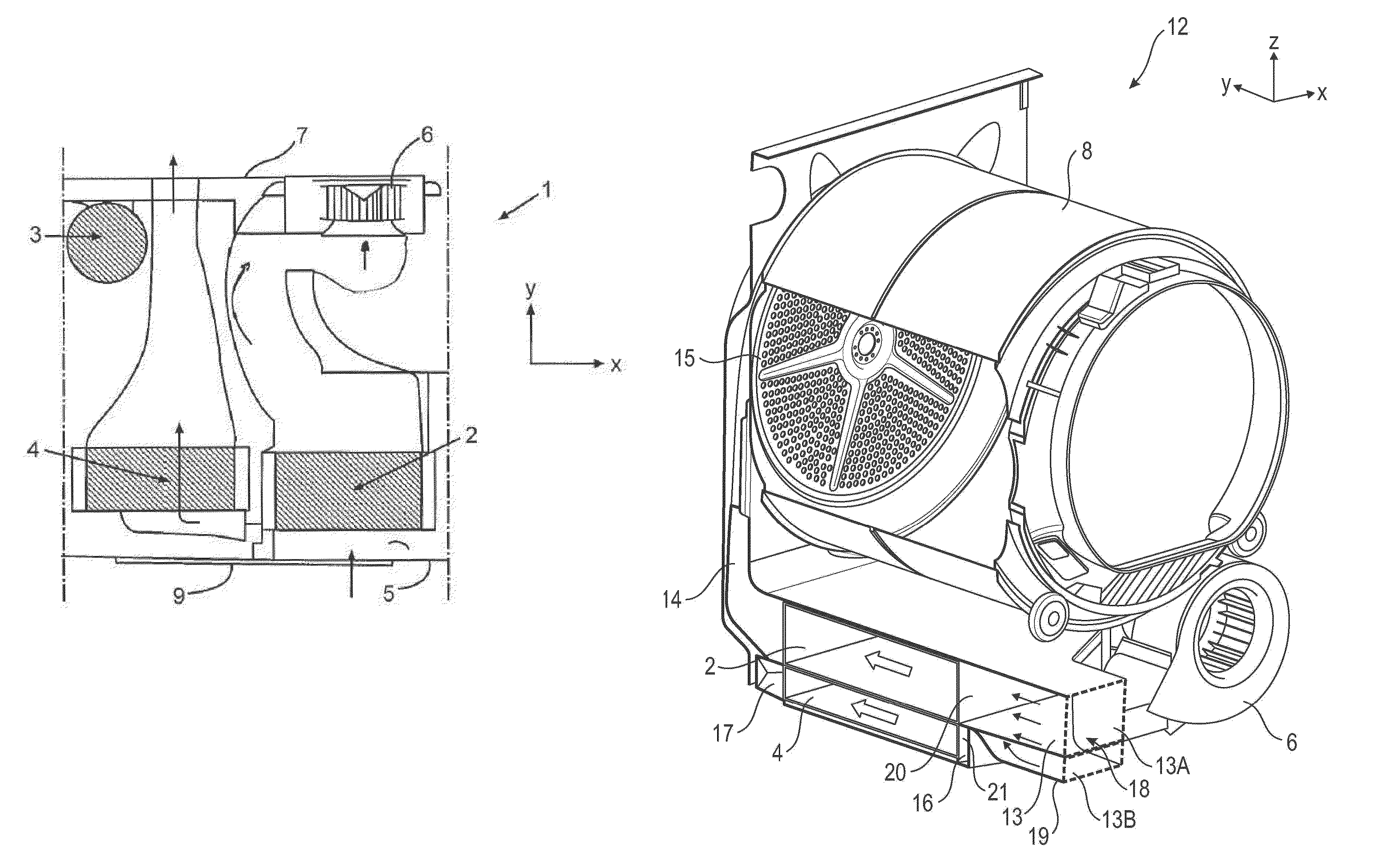
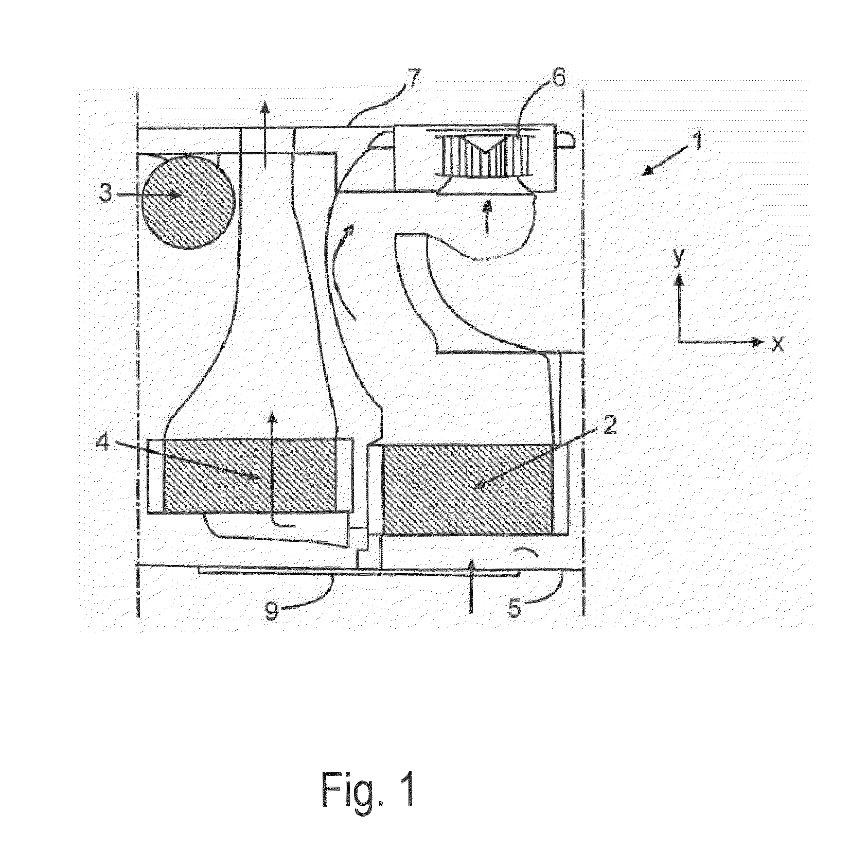
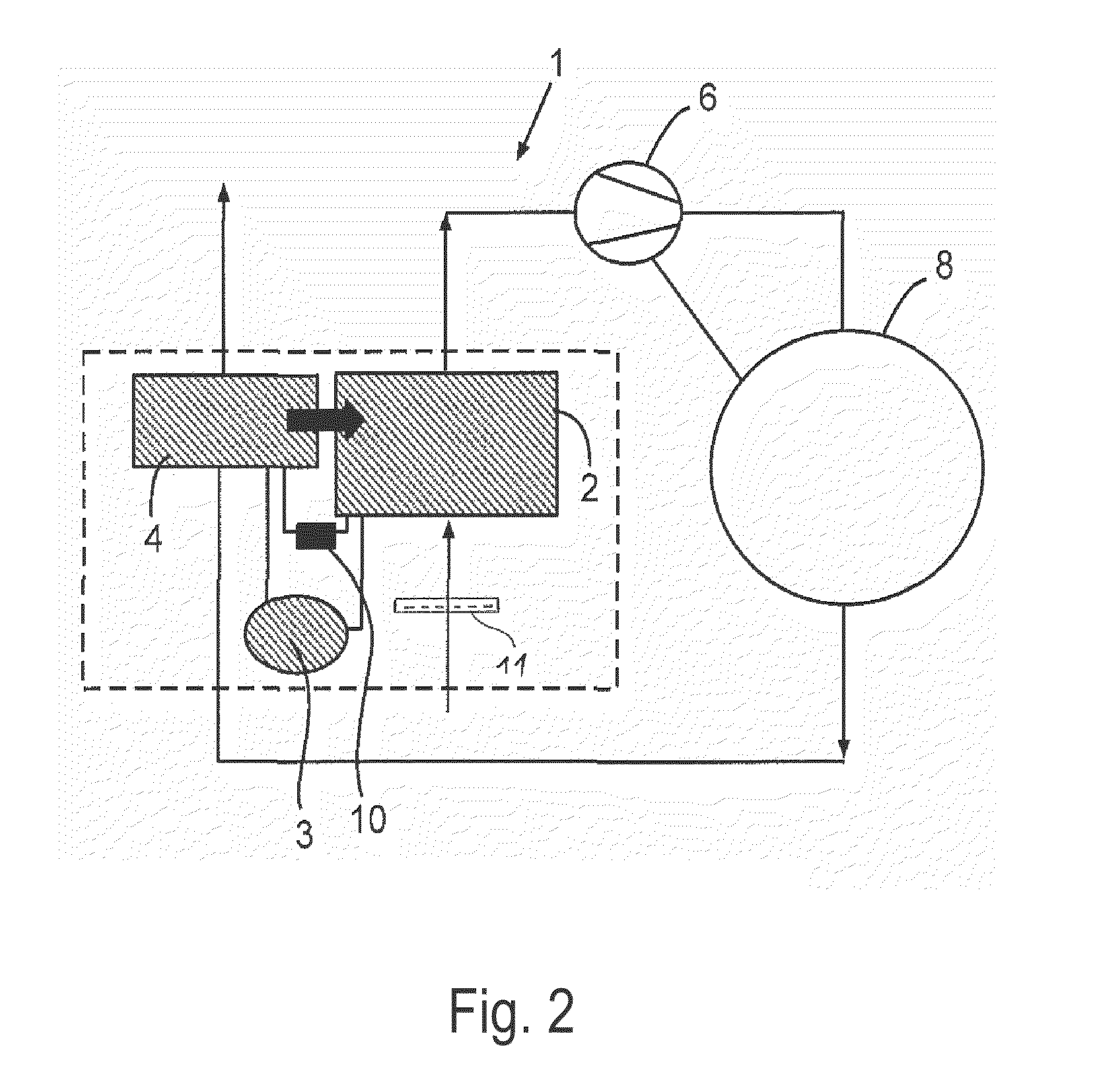
[0040]FIG. 1 shows a schematic top view of the exhaust air dryer 1, where only components essential for explanation of the invention are represented. The exhaust air dryer 1 comprises a heat pump 2, 3, 4, 10 with a condenser 2, which represents the heat source 2, a compressor 3, an evaporator 4, which represents the heat sink 4, and a throttle element 10. In this exemplary embodiment a compressor heat pump 2, 3, 4, 10 is accordingly provided. It is described in detail above, to which reference is made here. A process air fan 6 sucks the ambient air, which, insofar as it is employed in the exhaust air dryer 1 is also generally designated “process air”, as supply air through a frontal housing wall 5 via the condenser 2 and corresponding air ducts according to the arrow representation into the drum 8 functioning as the drying chamber 8 (see FIG. 2). After emerging from the drum 8, the moisture-laden process air is directed according to the arrow representation through the evaporator 4,...


PUM


Abstract

An exhaust air dryer with a drying chamber for items to be dried. The dryer includes a process air fan, a heat exchanger which includes a heat source, a heat sink of a heat pump, and a flushing device for flushing of a first inflow surface of the heat source and a second inflow surface of the heat sink with a liquid which is assigned to the heat source and the heat sink for removing of soil; and air ducts interconnecting the drying chamber, the process air fan, and the heat exchanger for conducting process air.

Description

BACKGROUND OF THE INVENTION[0001]The invention relates to an exhaust air dryer with a drying chamber for items to be dried, which has a process air fan and at least one heat exchanger, wherein the drying chamber, the process air fan and the heat exchanger are interconnected by means of air ducts for the conveying of process air.[0002]Such an exhaust air dryer follows from DE 30 00 865 A1.[0003]Dryers for items of laundry and items of a similar kind are generally embodied as exhaust air dryers or condensation dryers. In the case of exhaust air dryers a stream of air is sucked in from the environs of the dryer, heated, directed over items to be dried and subsequently expelled from the dryer as “exhaust air”. This exhaust air contains all the moisture removed from the items to be dried, and can therefore not simply be released into the building, as this moisture would precipitate out therein; rather, the exhaust air must be directed out of the building by means of a corresponding exhau...

Claims


Application Information

Patent Timeline
Patent Type & Authority Patents(United States)
IPC IPC(8): F26B11/00
CPCD06F58/206
Inventor GRUNERT, KLAUSKRAUSCH, UWE-JENSSTEFFENS, GUNTERSTOLZE, ANDREAS
Owner BOSCH SIEMENS HAUSGERATE GMBH
Why Eureka
Try Eureka