Exhaust air dryer with heat exchanger

a technology of exhaust air dryer and heat recovery, which is applied in the direction of drying machines, drying chambers/containers, light and heating equipment, etc., can solve the problems of reducing the airflow volume, deteriorating performance figures and energy consumption, and exhaust air dryers with heat recovery have failed to establish themselves in the marketplace, so as to reduce pressure losses

Active Publication Date: 2010-01-21
BSH BOSCH & SIEMENS HAUSGERAETE GMBH
View PDF6 Cites 39 Cited by
  • Summary
  • Abstract
  • Description
  • Claims
  • Application Information

AI Technical Summary

Benefits of technology

[0029]To reduce pressure losses in particular at the heat source, the process air fan can pre...

Problems solved by technology

In the case of a known condensation dryer with a heat pump, its heat sink is connected from the airflow perspective such that by far the majority of the dirt particles (fluff etc.) suspended in the process air is deposited thereupon, which leads to a reduction in the airflow volume and thus to a deterioration in the performance figures and energy consumption.
To date, exhaust air dryers with heat recovery have failed to establish themselves in the marketplace; exhaust air dryers are appreciated primarily as simple, low-cost dryers, whic...

Method used


Image

  • Exhaust air dryer with heat exchanger
  • Exhaust air dryer with heat exchanger
  • Exhaust air dryer with heat exchanger

Examples


Embodiment Construction

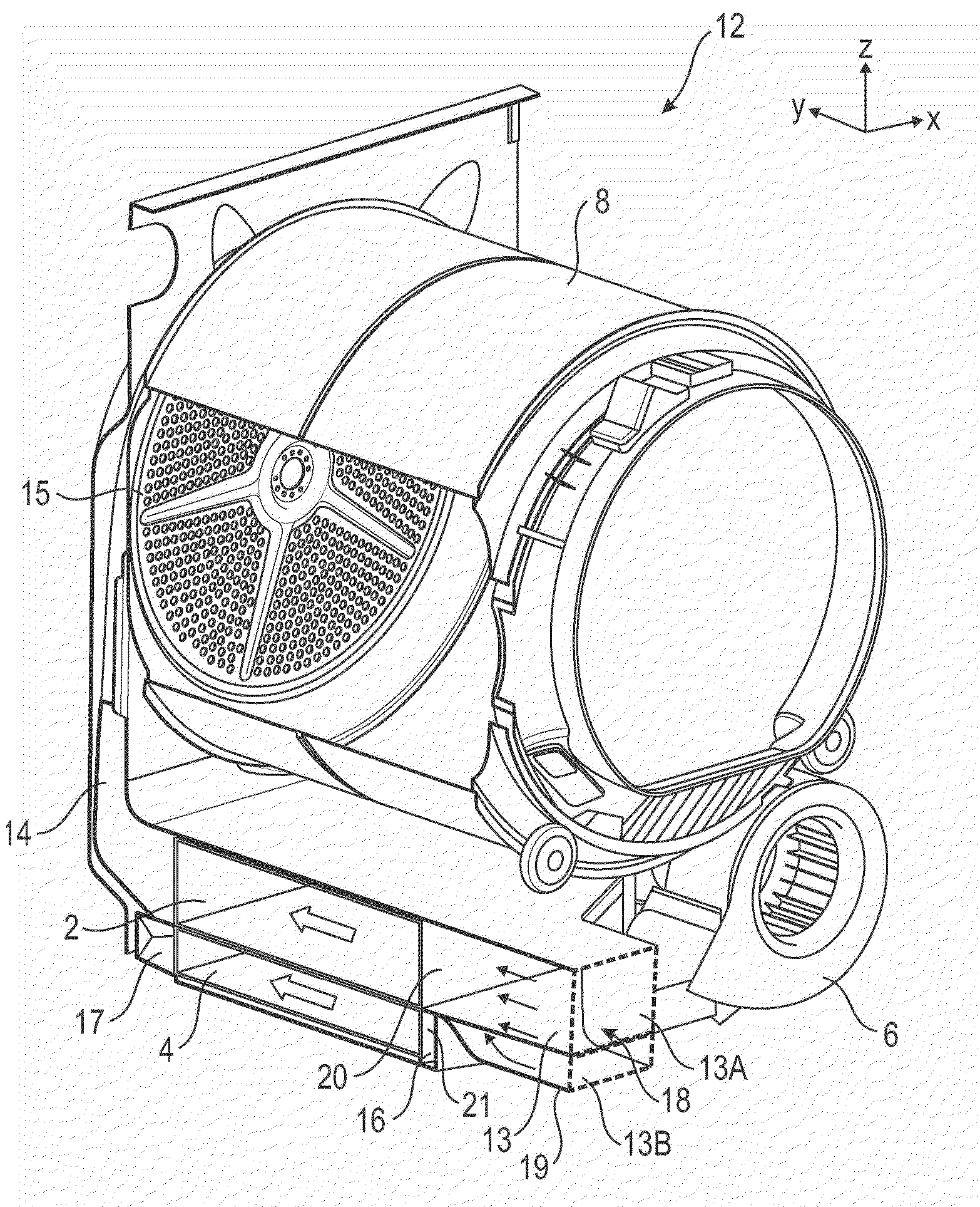
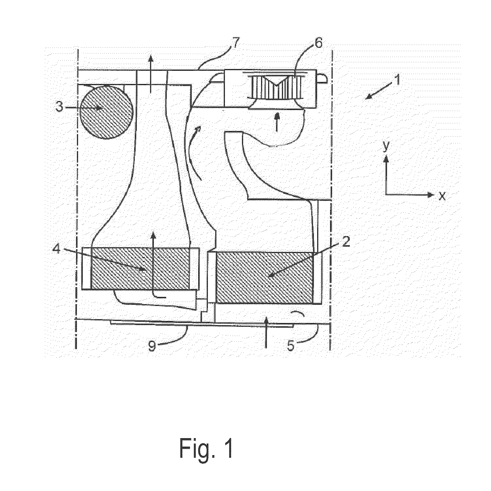
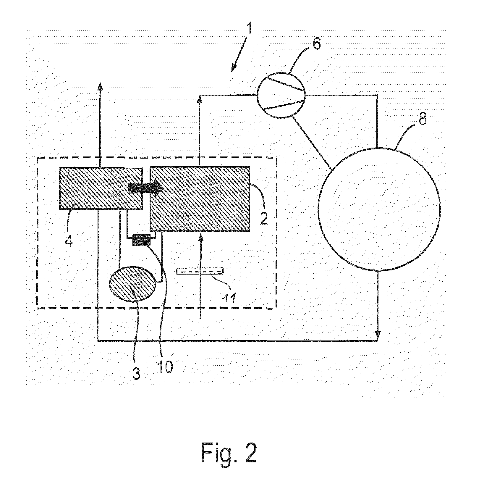
[0040]FIG. 1 shows a schematic top view of the exhaust air dryer 1, where only components essential for explanation of the invention are represented. The exhaust air dryer 1 comprises a heat pump 2, 3, 4, 10 with a condenser 2, which represents the heat source 2, a compressor 3, an evaporator 4, which represents the heat sink 4, and a throttle element 10. In this exemplary embodiment a compressor heat pump 2, 3, 4, 10 is accordingly provided. It is described in detail above, to which reference is made here. A process air fan 6 sucks the ambient air, which, insofar as it is employed in the exhaust air dryer 1 is also generally designated “process air”, as supply air through a frontal housing wall 5 via the condenser 2 and corresponding air ducts according to the arrow representation into the drum 8 functioning as the drying chamber 8 (see FIG. 2). After emerging from the drum 8, the moisture-laden process air is directed according to the arrow representation through the evaporator 4,...


PUM


Abstract

An exhaust air dryer with a drying chamber for items to be dried. The dryer includes a process air fan, a heat exchanger which includes a heat source, a heat sink of a heat pump, and a flushing device for flushing of a first inflow surface of the heat source and a second inflow surface of the heat sink with a liquid which is assigned to the heat source and the heat sink for removing of soil; and air ducts interconnecting the drying chamber, the process air fan, and the heat exchanger for conducting process air.

Description

BACKGROUND OF THE INVENTION[0001]The invention relates to an exhaust air dryer with a drying chamber for items to be dried, which has a process air fan and at least one heat exchanger, wherein the drying chamber, the process air fan and the heat exchanger are interconnected by means of air ducts for the conveying of process air.[0002]Such an exhaust air dryer follows from DE 30 00 865 A1.[0003]Dryers for items of laundry and items of a similar kind are generally embodied as exhaust air dryers or condensation dryers. In the case of exhaust air dryers a stream of air is sucked in from the environs of the dryer, heated, directed over items to be dried and subsequently expelled from the dryer as “exhaust air”. This exhaust air contains all the moisture removed from the items to be dried, and can therefore not simply be released into the building, as this moisture would precipitate out therein; rather, the exhaust air must be directed out of the building by means of a corresponding exhau...

Claims


Application Information

Patent Timeline
IPC IPC(8): F26B19/00F26B25/06F25B1/00
CPCD06F58/206
Inventor GRUNERT, KLAUSKRAUSCH, UWE-JENSSTEFFENS, GUNTERSTOLZE, ANDREAS
Owner BSH BOSCH & SIEMENS HAUSGERAETE GMBH
Why Eureka
Try Eureka