Multi-turn hydraulic actuator

a hydraulic actuator and multi-turn technology, applied in the direction of valve operating means/release devices, gearing, sustainable manufacturing/processing, etc., can solve the problems of difficult installation of manual switch levers in such a small space, affecting the operation of the valve, so as to minimize the use of electric power and facilitate installation

Active Publication Date: 2012-09-18
RPM TECH
View PDF9 Cites 5 Cited by
  • Summary
  • Abstract
  • Description
  • Claims
  • Application Information

AI Technical Summary

Benefits of technology

[0014]The present invention provides a multi-turn hydraulic actuator which solves the above problems of a conventional multi-turn electric actuator needing to be improved and has the new concepts making it easy to be installed and operated even in a limited space and making it possible to minimize the use of electric power.
[0015]It is therefore an object of the present invention to provide a multi-turn hydraulic actuator which uses a hydraulic motor, thereby using low electric power, significantly improving outputs and realizing fast response characteristics; which is formed in an assembly structure, thereby making it possible to detach / attach an operation part and a drive part so that only the drive part is installed in a limited space or in the spot where it is inconvenient to approach, and the operation part is separately installed at a desired place to be easily operated; which uses a manual mode switch to be input by a button, thereby minimizing a space for using the product; which uses a hydraulic pressure generator, thereby minimizing consumption of driving power; and which additionally includes a low-power processor needed for detecting the extent of opening, thereby minimizing standby electric power.

Problems solved by technology

Moreover, since all of the 3-phase electric motor, control unit, multi-unit, passageway switching unit and terminal unit forming the multi-turn electric actuator are structured in a single unit, it is impossible to install the manual switch lever in such a small space.
Further, in the analog detection method to perceive the extent of opening the valve and the drive of the actuator, an assembling process is very complicated since many gears are combined.
Therefore, this is regarded as a very annoying factor.
Therefore, high standby electric power is consumed at the moment when the actuator is not driven.

Method used


Image

  • Multi-turn hydraulic actuator
  • Multi-turn hydraulic actuator
  • Multi-turn hydraulic actuator

Examples


Embodiment Construction

[0029]The present invention will now be described more fully hereinafter with reference to the accompanying drawings, in which preferred embodiments of the invention are shown.

[0030]As used herein, the singular forms “a”, “an” and “the” are intended to include the plural forms as well, unless the context clearly indicates otherwise.

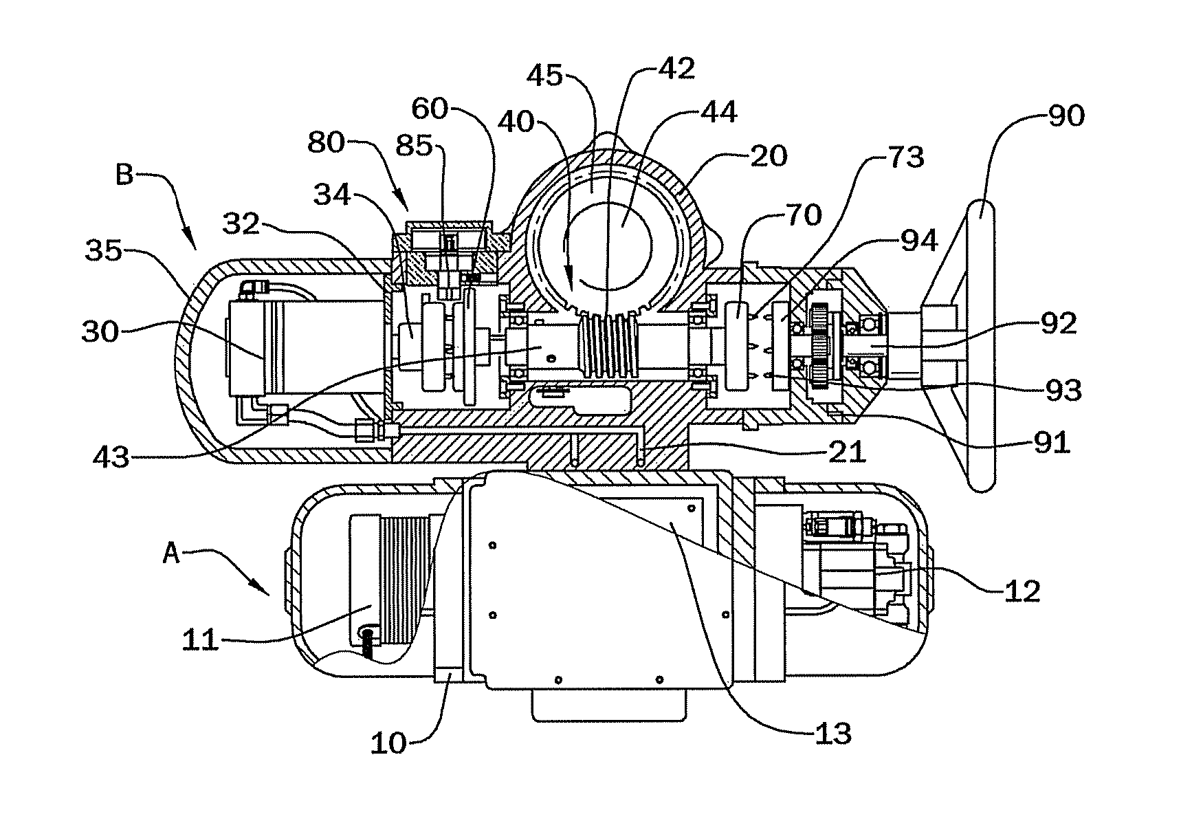
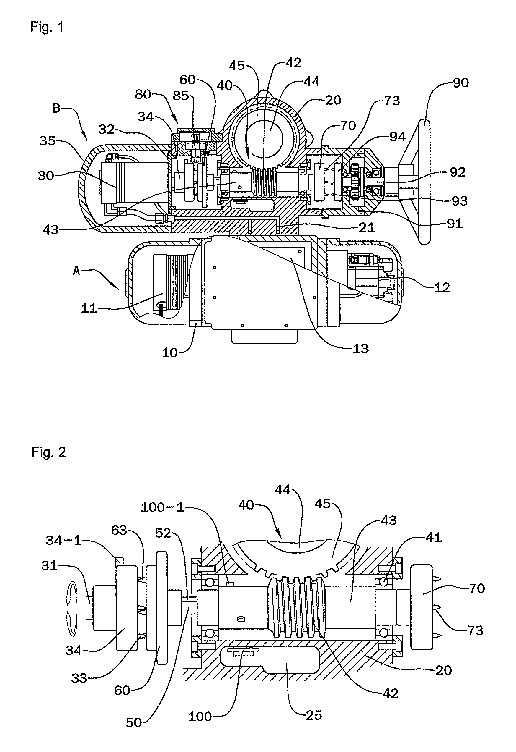
[0031]As illustrated in FIG. 1, a multi-turn hydraulic actuator according to the present invention is characterized in that hydraulic pressure generated by a hydraulic pressure generator 10 is supplied to a hydraulic motor 30 through a hydraulic channel 21 formed in a housing 20 of a drive part B or a separate hydraulic hose so that the hydraulic motor 30 is driven, a rotational force of the hydraulic motor 30 is transmitted to a worm shaft of a decelerator 40 directly connected to the hydraulic motor 30 so that a driving shaft 44 is rotated at a reduced speed, and the rotation of the worm shaft 43 is selectively manually operated by using a manual handle...


PUM


Abstract

There is provided a multi-turn hydraulic actuator used to open / close a passageway in ground and sea industries including general industrial machines, oil refineries and chemical plants and power generating plants, among others, and more particularly, a multi-turn hydraulic actuator comprising: a hydraulic motor and a decelerator, among others, whereby high torque is efficiently obtained by using low electric power, compared to a conventional electric actuator, and whereby an operation part and a drive part are freely attached to / detached from at a user's necessity.

Description

CROSS-REFERENCE TO RELATED PATENT APPLICATION[0001]This application claims the benefit of Korean Patent Application No. 10-2008-0095532, filed on Sep. 29, 2008, in the Korean Intellectual Property Office, the disclosure of which is incorporated herein in its entirety by reference.BACKGROUND OF THE INVENTION[0002]1. Field of the Invention[0003]The present invention relates to a multi-turn hydraulic actuator used to open / close a passageway in the ground and sea industries including general industrial machines, oil refineries and chemical plants, and power generating plants, among others, and more particularly, a technical field in which an actuator comprising a hydraulic motor and a decelerator is used to control the opening / closing of a valve which controls the flow of a fluid flowing through a path of a conduit, or a lock which is installed at a passageway.[0004]2. Description of the Related Art[0005]In general, major types of valve driving systems include a butterfly valve, a gate ...

Claims


Application Information

Patent Timeline
Patent Type & Authority Patents(United States)
IPC IPC(8): F16K31/05
CPCF16K31/05F16K31/14Y10T74/19037Y10T137/8242Y02P80/10F15B15/02F16H1/02
Inventor RHO, BYOUNG HOOSIM, HEE GOOBOK, MUN SULEE, JAE CHULKIM, PO YOUNG
Owner RPM TECH
Why Eureka
Try Eureka