System and method for transferring data from non-spread clock domain to spread clock domain

a technology of data transfer and spread clock, applied in the field of data transfer systems, can solve the problems of substantially affecting other components operating in proximity to the deserializer, electromagnetic interference (emi) problems, and emi emission at that particular frequency

Active Publication Date: 2012-09-18
MAXIM INTEGRATED PROD INC
View PDF3 Cites 14 Cited by
  • Summary
  • Abstract
  • Description
  • Claims
  • Application Information

AI Technical Summary

Problems solved by technology

Because of this, relatively high energy is concentrated in substantially a single frequency, which may result in electromagnetic interference (EMI) problems.
This may result in the emission of electromagnetic interference (EMI) at substantially that particular frequency.
This could adversely affect other components operating in proximity to the deserializer 104.

Method used


Image

  • System and method for transferring data from non-spread clock domain to spread clock domain
  • System and method for transferring data from non-spread clock domain to spread clock domain
  • System and method for transferring data from non-spread clock domain to spread clock domain

Examples


Embodiment Construction

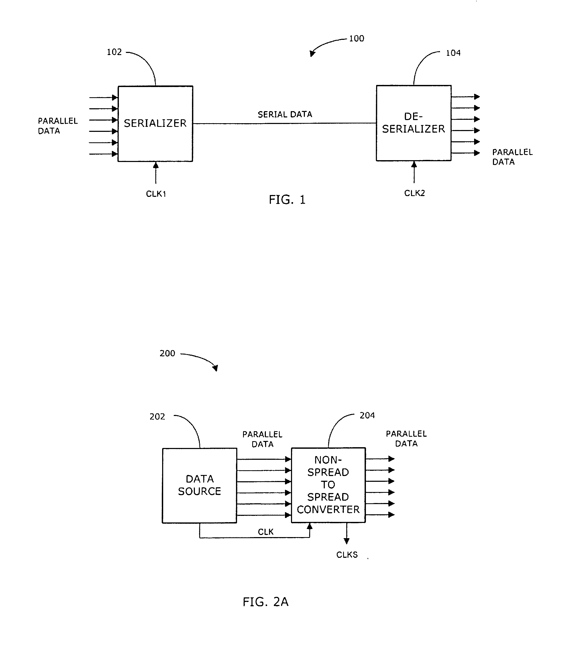
[0023]FIG. 2A illustrates a block diagram of an exemplary communication system 200 in accordance with another embodiment of the invention. In summary, the communication system 200 is particularly suited for reducing electromagnetic interference (EMI) by converter data in a non-spread domain to a spread domain. In particular, the communication system 200 comprises a data source 202 and a non-spread to spread converter 204. The data source 202 generates parallel data and transfer the data to the converter 204 using a substantially constant frequency (non-spread) clock signal CLK.

[0024]The converter 204, in turn, using the non-spread clock signal CLK to receive or clock in the parallel data. The converter 204, in turn, generates a frequency-modulated (spread) clock signal CLKS from the non-spread clock signal CLK. The converter 204 uses the spread clock signal CLKS to clock out the parallel data. Because the spread clock CLKS clocks out the parallel data, the energy of the output paral...


PUM


Abstract

An apparatus for transferring data in a non-spread domain to a spread domain. The apparatus comprises a first-in-first-out (FIFO) memory; a write pointer generator adapted to generate a write pointer for writing data into the FIFO memory in response to a non-spread clock signal; a spread-clock generator adapted to generate a spread clock signal based on the non-spread clock signal; a read pointer generator adapted to generate a read pointer for reading data from the FIFO memory in response to the spread clock signal; and a controller adapted to control the spread-clock generator in response to the read and write pointers indicating predetermined potential data overflow or underflow of the FIFO memory.

Description

FIELD OF THE INVENTION[0001]This invention relates generally to data transfer systems, and in particular, to a system and method for transferring data from a non-spread clock domain to a spread clock domain.BACKGROUND OF THE INVENTION[0002]In many applications, data is sent in a serial manner from a transmitting device to a receiving device. In order to properly receive the serial data, the receiving device typically needs timing information about when each datum, symbol or bit of the serial data is to be received. In some cases, the data is transmitted with an associated clock signal which provides the timing information needed for the receiving device to properly receive the data. In other cases, the receiving device develops the associated clock signal by sensing the phase of the incoming serial data. In both cases, the associated clock signal has a frequency that is substantially constant. Because of this, relatively high energy is concentrated in substantially a single frequenc...

Claims


Application Information

Patent Timeline
Patent Type & Authority Patents(United States)
IPC IPC(8): H04L7/00
CPCH04L7/02H04L7/005H04L25/05
Inventor ONER, MUSTAFA ERTUGRUL
Owner MAXIM INTEGRATED PROD INC
Why Eureka
Try Eureka