Method and apparatus for aligning the axle of a vehicle

a technology of axles and apparatus, applied in the direction of mechanical measuring arrangements, instruments, using mechanical means, etc., can solve the problems of excessive tire drag, reduced tire life, and reduced fuel economy, and achieve the effect of eliminating skew in axles and wheels

Inactive Publication Date: 2012-09-25
PORTA SCOTT S +1
View PDF12 Cites 3 Cited by
  • Summary
  • Abstract
  • Description
  • Claims
  • Application Information

AI Technical Summary

Benefits of technology

[0008]The present invention relates to a laser alignment system and especially to rear axle alignment to eliminate skew in the axle and wheels. A vehicle axle housing shim has a shim block having a tie bolt hole therein for receiving a tie bolt therein. The shim block is shaped to fit between a vehicle axle housing and a leaf spring. A pair of axle housing engaging lips are movably attached to opposite sides of the shim block and spaced therefrom and movable relative thereto. Each axle engaging lip has at least one threaded member passing therethrough and threaded into the shim block. The axle engaging lip is threadedly moved to move the axle housing relative to the leaf spring and vehicle chassis. Each axle engaging lip typically has a pair of threaded members passing therethrough and has a generally L-shaped cross-section holding the axle housing between the axle engaging lips. The leaf spring tie bolt extends through a leaf spring and into the shim block tie hole for holding the leaf spring relative to the movement of the axle housing by the axle housing engaging lips.

Problems solved by technology

However, a misaligned rear axle also results in reduced tire life and reduced fuel economy.
A misaligned rear axle causes excessive tire drag and creates undesirable lateral forces.
Because of the increased tire wear and reduced fuel economy, even small misalignments of the rear axle become particularly important for freight carrying vehicles that must travel long distances.
However, obtaining the proper alignment in an assembly line setting is difficult as are the minute adjustments that must be made quickly and accurately.
In addition, if a fixed axle housing is slightly bent, one wheel will have skew relative to the other wheels which will also increase tire wear on the one wheel while reducing fuel economy in the vehicle.
The thrust angle or axle offset causes both rear tires to point in the wrong direction and creates skew in the rear wheel assembly.

Method used


Image

  • Method and apparatus for aligning the axle of a vehicle
  • Method and apparatus for aligning the axle of a vehicle
  • Method and apparatus for aligning the axle of a vehicle

Examples


Embodiment Construction

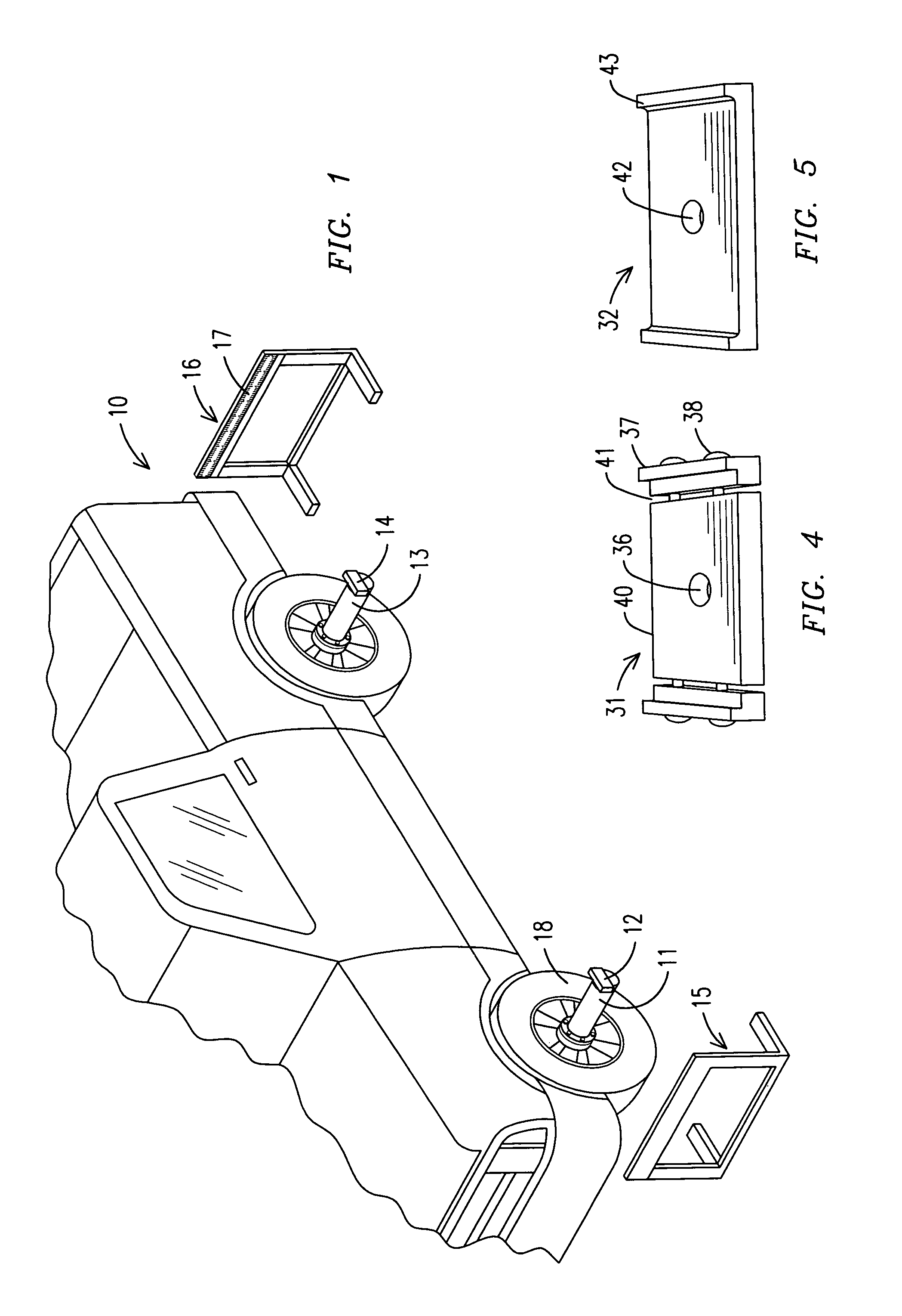
[0016]Referring to FIG. 1, a pickup truck 10 is illustrated having a laser supporting attachment 11 attached to a vehicle front wheel spindle or hub for supporting a laser 12. A laser supporting attachment 13 is attached to the rear axle spindle or hub and supports a rear axle laser 14. Lasers are attached to all four wheels of the vehicle during the alignment of the wheels and axles. The laser supporting attachments 11 and 13 for the vehicle wheel hub use the laser supporting attachment for a vehicle alignment system in accordance with the Loescher patent, U.S. Pat. No. 6,823,598. The target 15 is mounted in front of the vehicle 10 while a rear target 16 is mounted to the rear of a vehicle. Each target has a series of target gradations 17 thereon to which the light from lasers 12 and 14 are directed. During the laser alignment of the vehicles wheels 18, the front wheels are aligned for a caster, camber and toe and are aligned in accordance with the specifications for the vehicle to...


PUM


Abstract

An apparatus and method of aligning a vehicle's fixed rear axle relative to the vehicle frame and suspension elements uses an adjustable axle housing shim between one end of the axle housing and a leaf spring. One end of the axle is moved by the adjustable axle housing shim to remove any skew in the axle and wheels.

Description

BACKGROUND OF THE INVENTION[0001]The present invention relates to an apparatus and a method of aligning a vehicle's axles and especially to a method and apparatus for aligning a fixed axle relative to the frame and suspension elements of the vehicle.[0002]A proper aligned front end of a vehicle has long been a necessity for long tire life, handling ease and for achieving optimal fuel economy. The vehicle wheels need to travel in a straight line, with all wheels pointing in the same direction. That is, all four wheels must be square to each other and square to the road surface. All four wheels need to be parallel to one another and perpendicular to a common center line with the wheels straight up and down.[0003]Full attention has generally focused on the alignment of the front wheels. However, a misaligned rear axle also results in reduced tire life and reduced fuel economy. A misaligned rear axle causes excessive tire drag and creates undesirable lateral forces. Even in new trucks, ...

Claims


Application Information

Patent Timeline
Patent Type & Authority Patents(United States)
IPC IPC(8): G01B5/14
CPCG01B5/255G01B2210/16
Inventor PORTA, SCOTT S.LOESCHER, MICHAEL C.
Owner PORTA SCOTT S
Why Eureka
Try Eureka