
Distributed video coding apparatus and method capable of controlling encoding rate

a video coding and coding technology, applied in the field of distributed video coding (dvc) apparatus and methods, can solve the problems of reducing increasing the delay and complexity of the feedback channel, and limiting the processing ability and the life span of the battery of cameras and sensors, so as to reduce the number of feedbacks, reduce the delay and complexity of the decoder, and increase the complexity of the encoder

Inactive Publication Date: 2012-09-25
ELECTRONICS & TELECOMM RES INST
View PDF4 Cites 0 Cited by
  • Summary
  • Abstract
  • Description
  • Claims
  • Application Information

AI Technical Summary

Benefits of technology

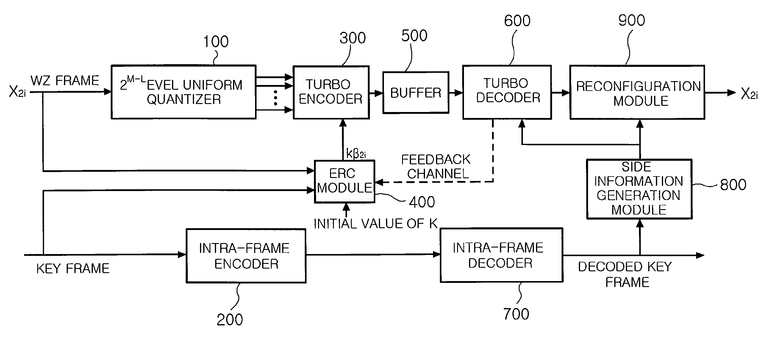
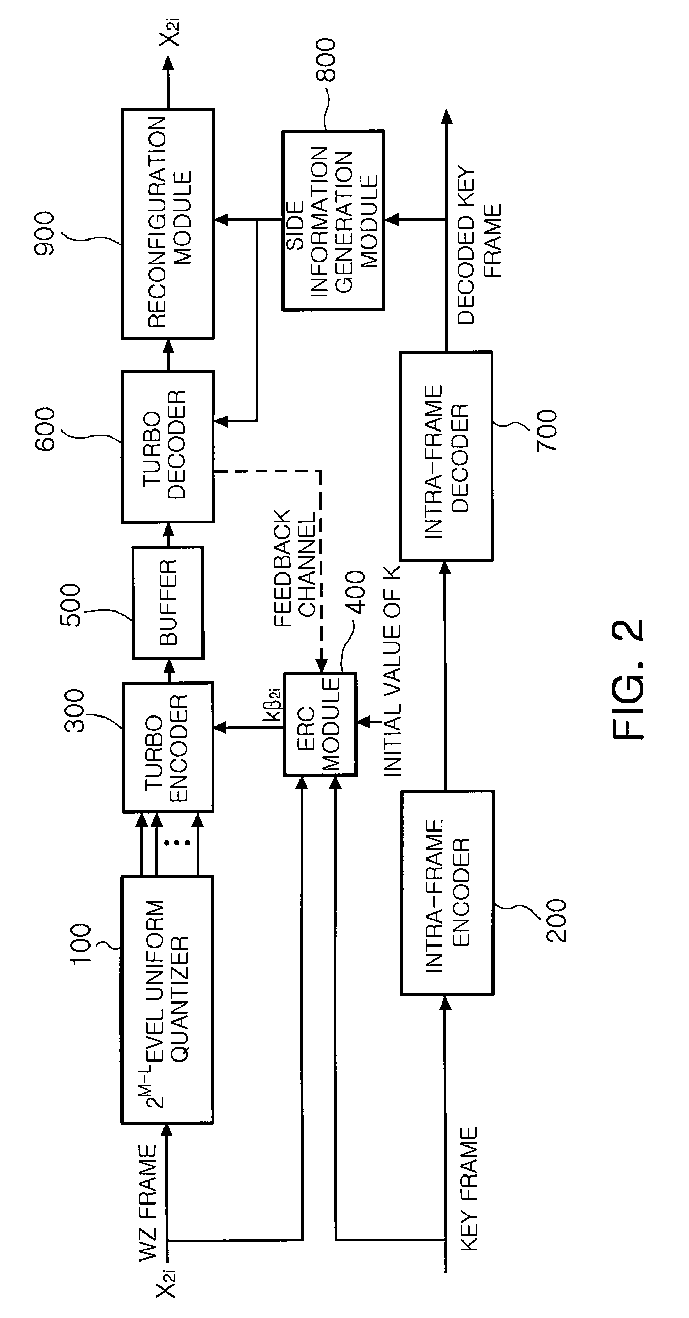
The present invention provides a coding apparatus and method that can estimate the bit rate of a decoder based on the motion complexity of a video image and control the encoding rate accordingly. This reduces the number of feedbacks or perfectly removes feedback channels, resulting in a more efficient coding process. The apparatus includes an intra-frame encoder, an encoder rate control module, and a turbo encoder. The method includes calculating motion complexity, estimating the bit rate, and controlling the encoding rate. The invention simplifies the bit rate estimation process and reduces decoding delays and complexity.

Problems solved by technology

However, in applications using a wireless sensor network or small camera chips, terminals such as cameras and sensors have a limitation in processing abilities and the life span of batteries.
Accordingly, use of feedback channels increases delays and complexity.
However, due to a limitation on performance and poor flexibility thereof, the PRISM has not been used in these days.
However, most of the described methods have fundamental defects caused by using feedback channels.
Though it is possible to properly maintain a bit rate by using feedback channels, unnecessary delays occur and an amount of calculation performed at the decoder increases.
However, since the encoder is unaware of the side information generated at the decoder, a proper bit rate of Wyner-Ziv frames that should be sent to the decoder is unknown.
However, a considerable amount of calculation should be executed at the encoder.
Accordingly, as a bit plane becomes higher, a noise level of side information increases.
As described above, since conventional DVC methods use feedback channels, decoding is delayed and complexity of a decoder increases.
However, instead of solving the problems, an amount of calculation executed at an encoder increases to estimate a bit rate of the decoder, which is another problem.

Method used


Image

  • Distributed video coding apparatus and method capable of controlling encoding rate
  • Distributed video coding apparatus and method capable of controlling encoding rate
  • Distributed video coding apparatus and method capable of controlling encoding rate

Examples


Embodiment Construction

[0042]Hereinafter, exemplary embodiments of the present invention will now be described in detail with reference to the accompanying drawings.

[0043]Only, in describing operations of the exemplary embodiments in detail, when it is considered that a detailed description on related well-known functions or constitutions unnecessarily may make essential points of the present invention be unclear, the detailed description will be omitted. Also, in the drawings, the same reference numerals are used throughout to designate the same or similar components.

[0044]Also the term of “module” indicates a unit for processing a certain function or operation, which can be embodied by software, hardware, or a combination of software and hardware.

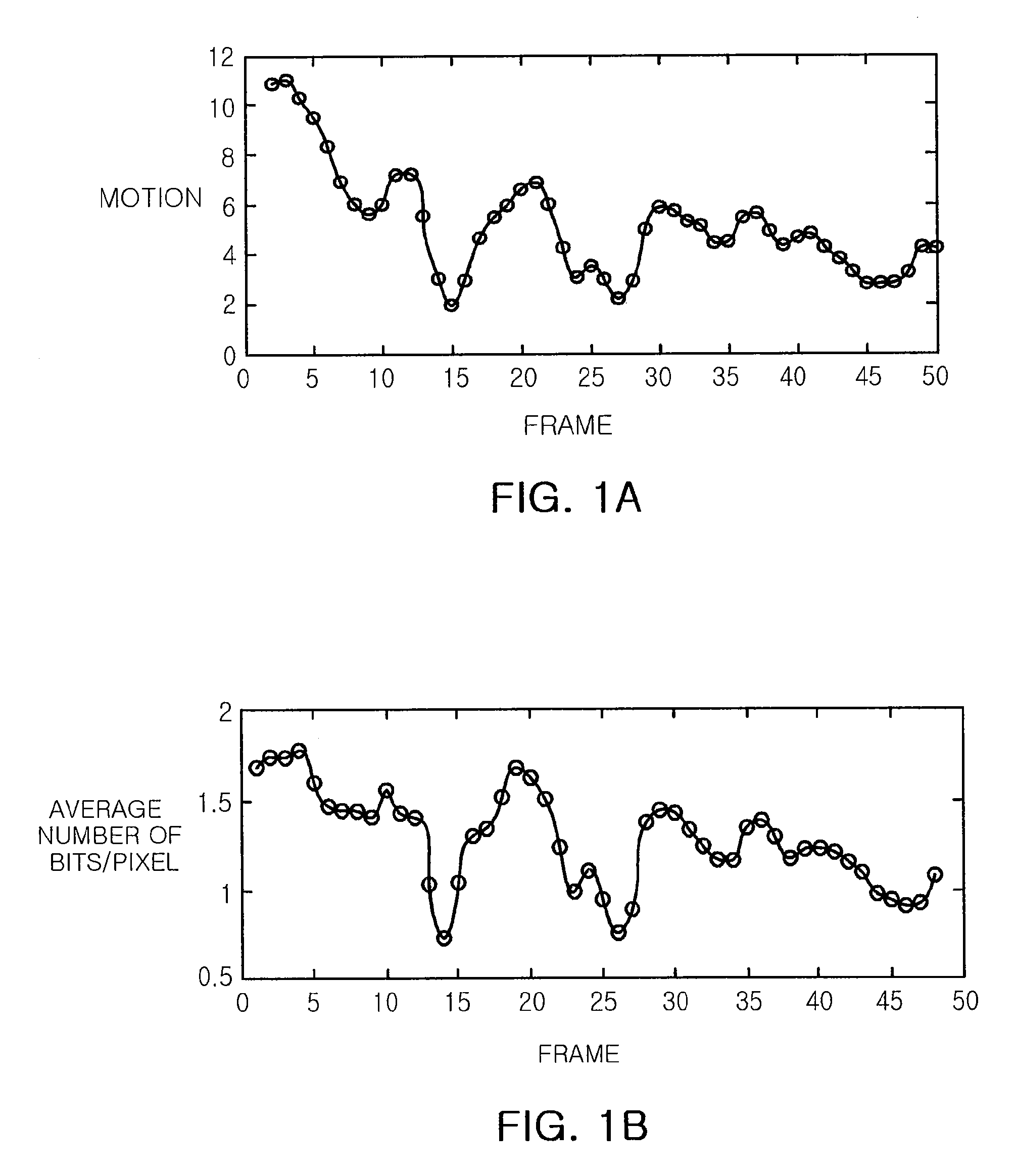
[0045]Before describing a distributed video coding (DVC) apparatus capable of controlling a bit rate, according to an exemplary embodiment of the present invention, referring to FIGS. 1A and 1B, there will be described a correlation between motion complexity of...


PUM


Abstract

There are provided a distributed video coding apparatus and method capable of controlling an encoding rate, the apparatus including: an intra-frame encoder encoding a key frame and outputting a bit stream of the encoded key frame; an encoder rate control (ERC) module calculating a bit rate according to motion complexity of a present Wyner-Ziv (WZ) frame by using a correlation between the motion complexity and the bit rate; and a turbo encoder encoding the present WZ frame by the bit rate calculated at the ERC module and outputting the encoded WZ bit stream.

Description

CROSS-REFERENCE TO RELATED APPLICATIONS[0001]This application claims the priority of Korean Patent Application No. 10-2007-0128277 filed on Dec. 11, 2007, in the Korean Intellectual Property Office, the disclosure of which is incorporated herein by reference.BACKGROUND OF THE INVENTION[0002]1. Field of the Invention[0003]The present invention relates to a distributed video coding (DVC) apparatus and method capable of improving video coding performance, and more particularly, to a DVC apparatus and method having low complexity by controlling an encoding rate.[0004]This work was supported by the IT R&D program of MIC / IITA [2005-S-077-03, titled: Development of On-chip Network-based SoC Platform].[0005]2. Description of the Related Art[0006]Nowadays, there are many applications related on video coding technology capable of accurately transmitting an image received from a camera. However, in applications using a wireless sensor network or small camera chips, terminals such as cameras an...

Claims


Application Information

Patent Timeline
Patent Type & Authority Patents(United States)
IPC IPC(8): H04B1/66
CPCH04N19/115H04N19/137H04N19/61H04N19/14
Inventor CHANG, JUNE YOUNGCHO, HAN JINLEE, GUEE SANGBAE, YOUNG HWANJEON, IN SANKIM, WON JONGLEE, MI YOUNGKIM, JU YEOB
Owner ELECTRONICS & TELECOMM RES INST
Learn More