Fire resistant PV shingle assembly

a technology of pv shingle and pv body, which is applied in the direction of photovoltaic supports, pv power plants, sustainable buildings, etc., can solve the problems of low operating efficiency, low operating efficiency, and inability to use pv modules, so as to improve energy conversion rate and reduce the operating temperature of the pv body

Active Publication Date: 2012-10-02
SUNPOWER CORPORATION
View PDF56 Cites 82 Cited by
  • Summary
  • Abstract
  • Description
  • Claims
  • Application Information

AI Technical Summary

Benefits of technology

[0006]The present invention is directed to a fire resistant PV shingle assembly which can be economically mounted directly to a support surface, such as a sloped roof, in a simple manner to create an aesthetically pleasing structure that integrates well with, for example, conventional roofing tiles. The PV shingle assembly can be constructed to be a substitute for a conventional shingle to eliminate the need for mounting the PV shingle assembly on top of a shingled, or other water-shedding, roof surface. The PV shingle assembly may also be constructed to achieve a Class A fire rating at least partially through the use of a fire shield below the PV body. The PV shingle assembly may also be constructed to provide a ventilation path beneath the PV body to reduce the operating temperature of the PV body and thus potentially improving energy conversion rates.

Problems solved by technology

Primary among the factors are ease of installation, cost and aesthetics.
However, photovoltaic shingle systems have not been as widely accepted as hoped-for because 1) PV mounted integrally with the building roof as shingles operate at higher temperatures, causing a reduction in PV electrical output due to an inverse relationship between temperature and PV efficiency, as well as increasing the temperature of the roofing surface; 2) the same higher operating temperatures approach or exceed the upper limit of the warranted PV operating temperature and serve to shorten the useful life of the PV shingle; 3) some products call for electrical connections between shingles to be made under the roof deck, requiring holes to be drilled through the roof deck which increases the likelihood of water leaks; 4) there has been poor aesthetic match of PV shingles in conjunction with the non-PV areas of the roof; 5) some PV shingles have been limited to amorphous silicon PV technology, which suffer from a low operating efficiency; and 6) the value of the PV shingle has typically been limited to the electrical output of the PV plus the material value of displaced conventional shingles when the product displaces conventional shingles.
However, this approach has not been used on PV modules that are intended to integrate with conventional concrete roofing shingles.

Method used


Image

  • Fire resistant PV shingle assembly
  • Fire resistant PV shingle assembly
  • Fire resistant PV shingle assembly

Examples


Embodiment Construction

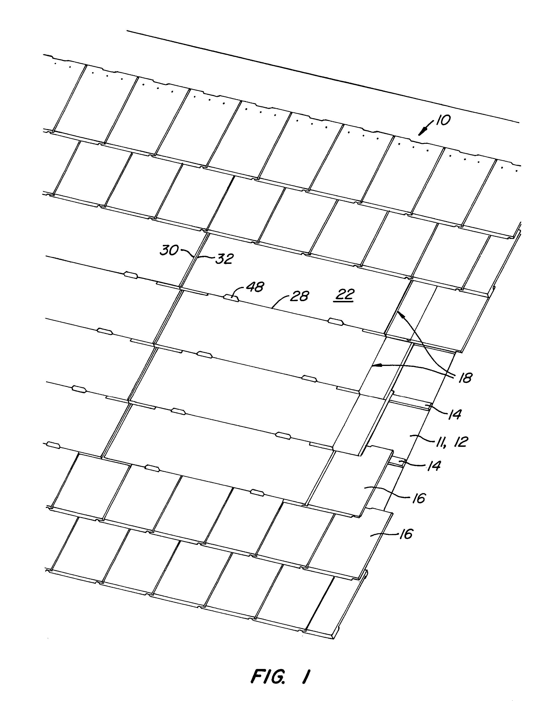
[0042]FIG. 1 illustrates a roofing system 10 including a roofing support surface 11, support surface 11 comprising a waterproof and radiant barrier layer 12. Layer 12 may be a conventional underlayment, such as VersaShield® SB2S Fire Barrier Fabric from Elk Technologies, Inc. A series of laterally extending battens 14 are mounted to support surface 11 over layer 12. Support surface 12 is covered by conventional concrete tiles 16, such as MonierLifetile sold by MonierLifetile LLC of Irvine, Calif., and an array of photovoltaic (PV) shingle assemblies 18. As used in this application, a shingle covers products used to cover a wall or an inclined roof, or other non-horizontal surfaces, in which the lower end of one shingle overlaps the upper end of an adjacent shingle.

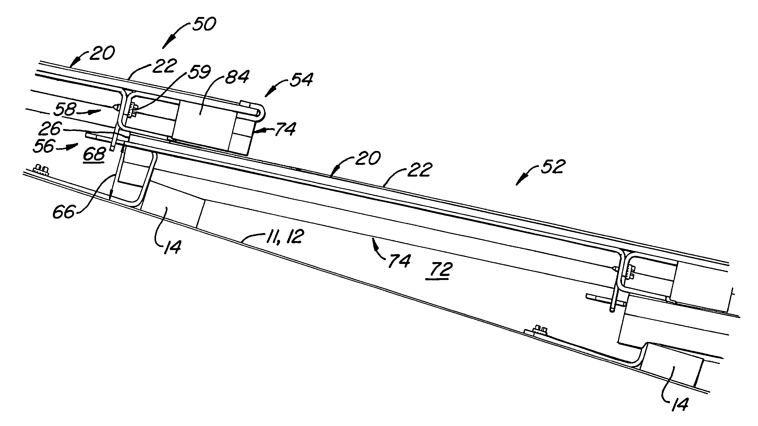
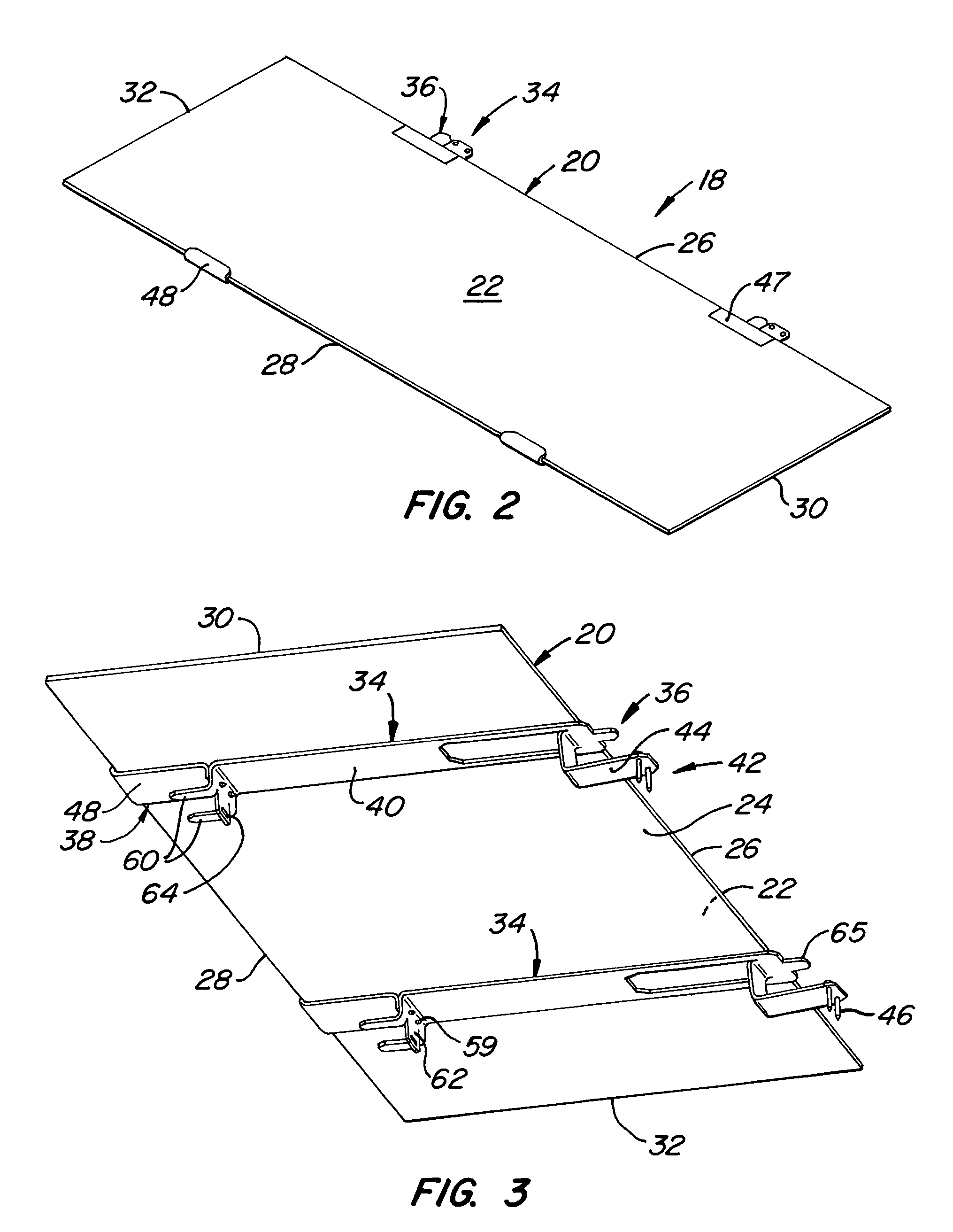
[0043]FIGS. 2 and 3 are enlarged top and bottom isometric views of a shingle assembly shown in FIG. 1. Each shingle assembly 18 comprises a shingle body 20 having upper and lower surfaces 22, 24, an upper edge 26, a lower ...


PUM


Abstract

A fire resistant PV shingle assembly includes a PV assembly, including PV body, a fire shield and a connection member connecting the fire shield below the PV body, and a support and inter-engagement assembly. The support and inter-engagement assembly is mounted to the PV assembly and comprises a vertical support element, supporting the PV assembly above a support surface, an upper interlock element, positioned towards the upper PV edge, and a lower interlock element, positioned towards the lower PV edge. The upper interlock element of one PV shingle assembly is inter-engageable with the lower interlock element of an adjacent PV shingle assembly. In some embodiments the PV shingle assembly may comprise a ventilation path below the PV body. The PV body may be slidably mounted to the connection member to facilitate removal of the PV body.

Description

STATE SPONSORED RESEARCH OR DEVELOPMENT[0001]This invention was made with State of California support under California Energy Commission contract number 500-00-034. The Energy Commission has certain rights to this invention.CROSS-REFERENCE TO OTHER APPLICATIONS[0002]This application is related to U.S. patent application Ser. No. 10 / 872,126 filed 18 Jun. 2004, entitled Shingle Assembly with Support Bracket.BACKGROUND OF THE INVENTION[0003]The widespread use of photovoltaic (PV) systems mounted to homes, businesses and factories is generally considered to be a desirable goal. Several factors are believed to be critical to the acceptance of PV systems, in particular by the individual homeowner. Primary among the factors are ease of installation, cost and aesthetics. One way of addressing both cost and aesthetics has been through the use of photovoltaic shingle assemblies. One way such shingle assemblies address the cost issue is by being used as a replacement for conventional shingles,...

Claims


Application Information

Patent Timeline
Patent Type & Authority Patents(United States)
IPC IPC(8): E04H14/00
CPCE04D13/172H01L31/04H02S20/23E04D2001/3447Y02E10/50Y02B10/12E04D1/29Y02B10/10
Inventor LENOX, CARL J. S.
Owner SUNPOWER CORPORATION
Why Eureka
Try Eureka