Method of accessing two lateral recesses

a lateral recess and access method technology, applied in the field of devices and methods for improving injection systems, can solve the problems of reducing the chances of inadvertent injection of substances into blood vessels, inadvertent damage to structures, etc., and reducing the chances of inadvertent injection. , the effect of minimizing safety concerns

Inactive Publication Date: 2012-10-02
LAURIMED
View PDF231 Cites 87 Cited by
  • Summary
  • Abstract
  • Description
  • Claims
  • Application Information

AI Technical Summary

Benefits of technology

[0024]The present invention incorporates features that address each of the risks listed above. The devices and methods described herein include a catheter with a blunt distal tip and an injection port that allow drugs or other substances to disperse at a target site while minimizing safety concerns. The construction of the catheter decreases the chances of inadvertently injecting substances into a blood vessel as well as inadvertently damaging structures because of incorrect placement of a needle.
[0027]The methods, systems and devices permit the physician to access lateral recesses in vertebral bodies directly. This allows the delivery of medication directly at the source of pathology. The present methods, systems and devices enable the physician to position a tip of a needle safely away from the exiting nerve root prior to advancing a flexible, curved, elastic catheter into the foramen and lateral recess to inject the medication directly into the site of pathology. The injection tube described herein (typically a small caliber catheter) traverses the foramen, thereby eliminating or dramatically reducing the incidence of nerve root contact and the associated sequelae as discussed above. In addition, the physician can determine the path of travel from outside of the body either by visual indicators or tactile indicators.
[0033]The systems can include additional safety features to minimize inadvertent shearing of the injection tube by the needle. For example, the needle tip can include a bevel tissue piercing shape having a heel at a proximal end. In some variations, the heel can include a recessed section that minimizes engagement between the heel and the injection tubing. Additional features include at least one wire located within the injection lumen. Where one or more wires can be a radiopaque wire, a shape memory alloy or a super elastic alloy (or a combination thereof).

Problems solved by technology

The construction of the catheter decreases the chances of inadvertently injecting substances into a blood vessel as well as inadvertently damaging structures because of incorrect placement of a needle.

Method used


Image

  • Method of accessing two lateral recesses
  • Method of accessing two lateral recesses
  • Method of accessing two lateral recesses

Examples


Embodiment Construction

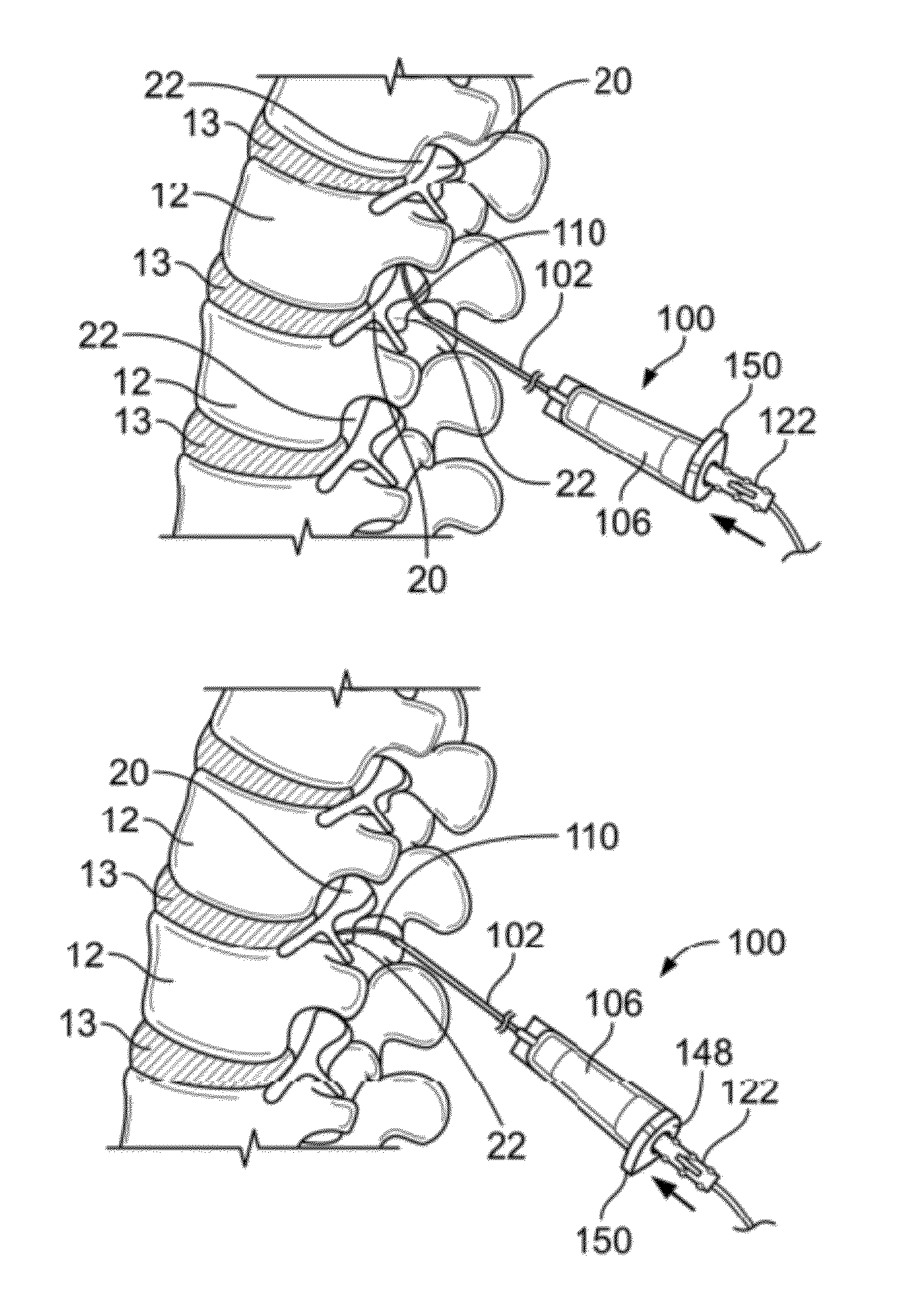
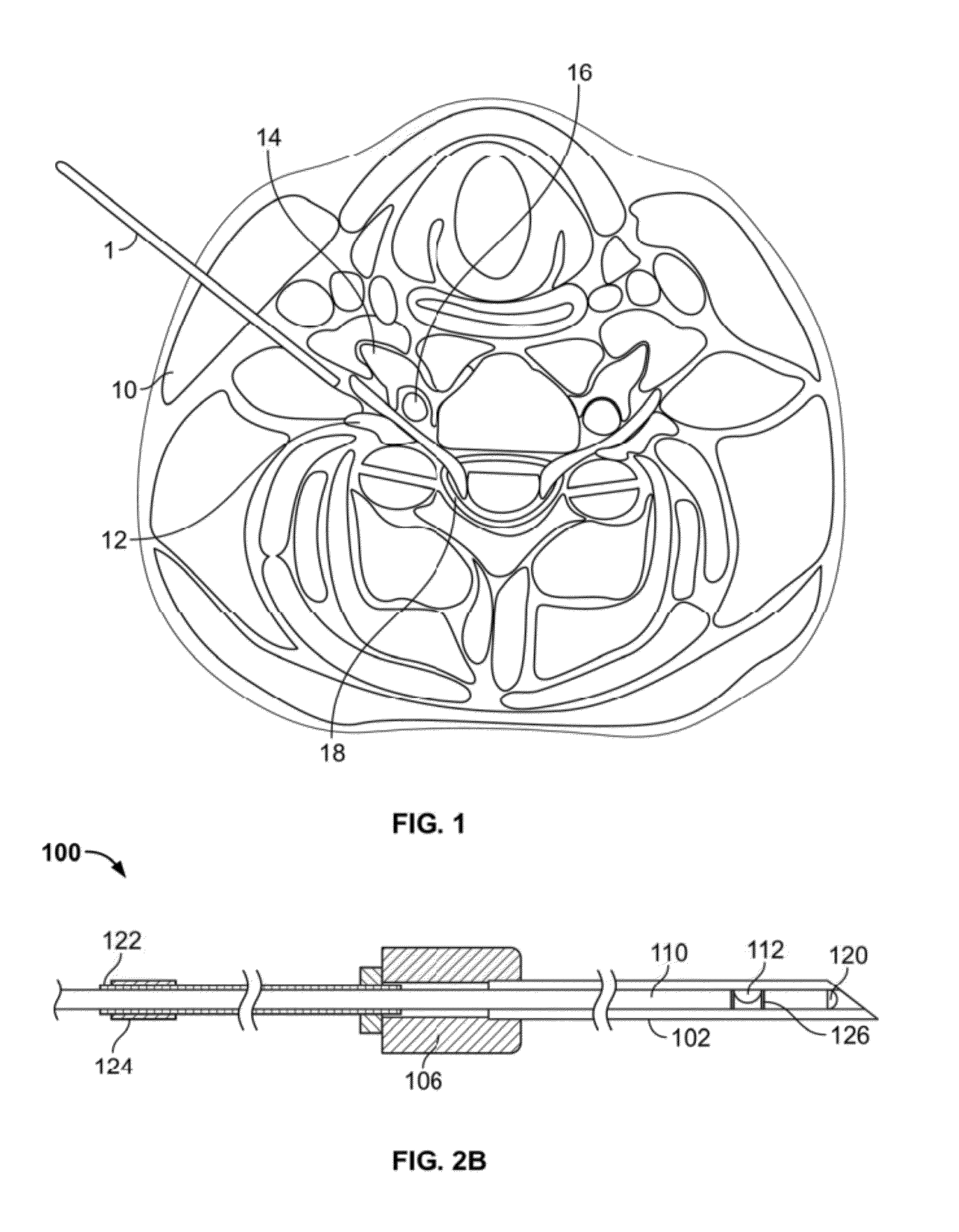
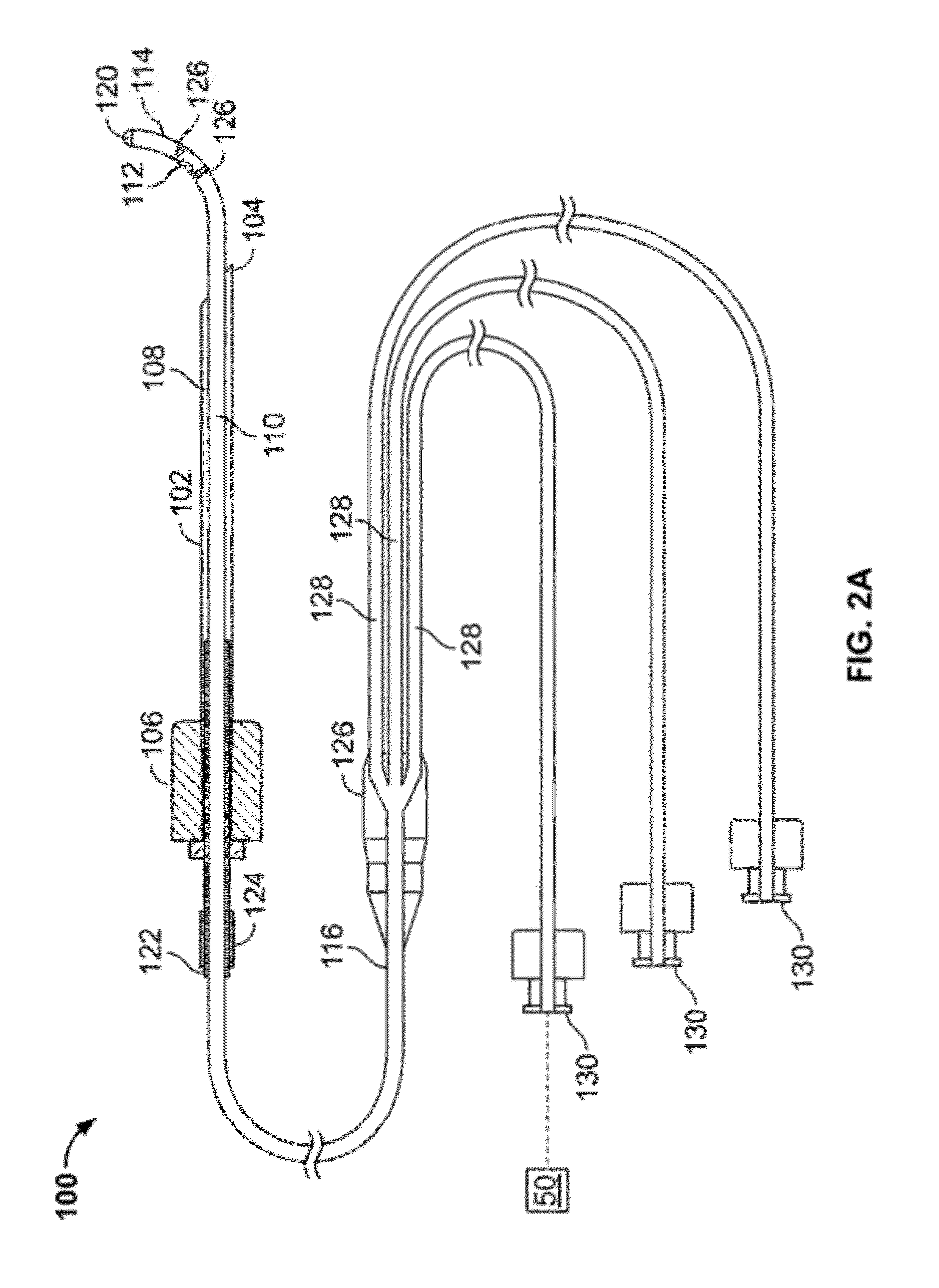
[0054]FIG. 1 illustrates a variation of an injection system 100. Although the systems and methods described herein are often described as being used as a cervical injection system or for the cervical region of the spine, the device and methods may be applied in a broader and to various other parts of the spine as well as anatomic structures where the features of the system may provide useful.

[0055]As shown in FIG. 1, the system 100 includes a cannula or needle cannula 102 where a distal tip 104 of the needle cannula 102 is sharp so that an operator may advance the cannula 102 through tissue to reach the intended target site. The needle cannula 102 may optionally include a hub 106. The hub 106 may be a common polymeric hub that is molded, bonded, or otherwise affixed to the needle cannula 102. Alternatively, though not shown, the hub 106 may comprise a section of the needle cannula 102 itself. In any case, in some variations of the system 100, the hub 106 provides an ergonomic surfac...


PUM


Abstract

Device and method are provided for diagnosing and treating diseases and injuries to the spine by injecting drugs into the diseased or injured area. The device and method of the subject invention provide improvements to patient and operator safety, along with ease-of-use and convenience improvements over conventional techniques.

Description

RELATED APPLICATIONS[0001]This is a non-provisional application of U.S. Provisional Application No. 61 / 123,028 filed Apr. 2, 2008. The contents of which are incorporated herein by reference in their entirety.FIELD OF THE INVENTION[0002]The present invention is drawn to devices and methods for improved injection systems. Variations of the devices and methods of the injection systems provide atraumatic injection delivery within a spinal column while minimizing the likelihood of causing adverse events.BACKGROUND OF THE INVENTION[0003]Annually, millions of Americans suffer from significant spine related pain and discomfort. Where the cervical, thoracic, and lumbar vertebrae and discs can be the source of this pain and discomfort. In one estimate, pain perceived in the neck or upper limbs that is caused by irritation in the nerves that exit the cervical spine through the foramen affects a population of approximately 1 person per 1000 per year. As a result, every year physicians in the Un...

Claims


Application Information

Patent Timeline
Patent Type & Authority Patents(United States)
IPC IPC(8): A61M31/00
CPCA61B17/3401A61M25/0041A61M25/007A61M25/065A61B17/3478A61B2017/00331
Inventor SAAL, JEFFREY ALANSAAL, JOEL STUARTDUBOIS, BRIAN ROBERTNIELSEN, JAMES T.
Owner LAURIMED
Why Eureka
Try Eureka