Fiber-fed advanced pulsed plasma thruster (FPPT)

a pulsed plasma and fiber-fed technology, applied in the field of fiber-fed advanced pulsed plasma thrusters, can solve the problems of high mass and small propellant mass, and achieve the effect of minimizing range safety concerns and lowering system specific mass

Active Publication Date: 2022-02-08
CU AEROSPACE
View PDF23 Cites 0 Cited by
  • Summary
  • Abstract
  • Description
  • Claims
  • Application Information

AI Technical Summary

Benefits of technology

[0010]The present invention is directed to a Fiber-fed Pulsed Plasma Thruster (FPPT). The thruster replaces the spring-fed state of the art Teflon™ feed system with a motor-driven fiber feed system, which pulls a flexible Teflon fiber from a spool. Additionally, an innovative, highly parallel ceramic capacitor bank dramatically lowers system specific mass. As used herein the fiber propellant can be a Teflon™ or PTFE equivalent.
[0011]The Fiber-fed Pulsed Plasma Thruster (FPPT) will enable low orbit, cis-lunar and deep space missions for small satellites. FPPT technology utilizes a motor to feed PTFE fiber to its discharge region, enabling class-leading PPT propellant throughput and variable exposed fuel area. An innovative, highly parallel ceramic capacitor bank dramatically lowers system specific mass. FPPT is inherently safe; its non-pressurized, non-toxic, inert propellant and construction materials minimize range safety concerns. Estimates are that a 1-liter (10 cm×10 cm×10 cm, or 1 U) volume FPPT thruster package may provide as much as 10,000 N-s total impulse, enabling 1.4 km / s delta-V for an 8 kg CubeSat. CU Aerospace (Applicant) is presently developing a 1 U integrated system including the advanced thruster head with igniter system, PTFE fiber feed system, power processing unit, and control electronics.

Problems solved by technology

While classic pulsed plasma thruster (hereinafter “PPT’) propulsion system technology is mature, it has historically been limited by its high mass and small propellant load to precision pointing and small delta-V applications.

Method used


Image

  • Fiber-fed advanced pulsed plasma thruster (FPPT)
  • Fiber-fed advanced pulsed plasma thruster (FPPT)
  • Fiber-fed advanced pulsed plasma thruster (FPPT)

Examples


Embodiment Construction

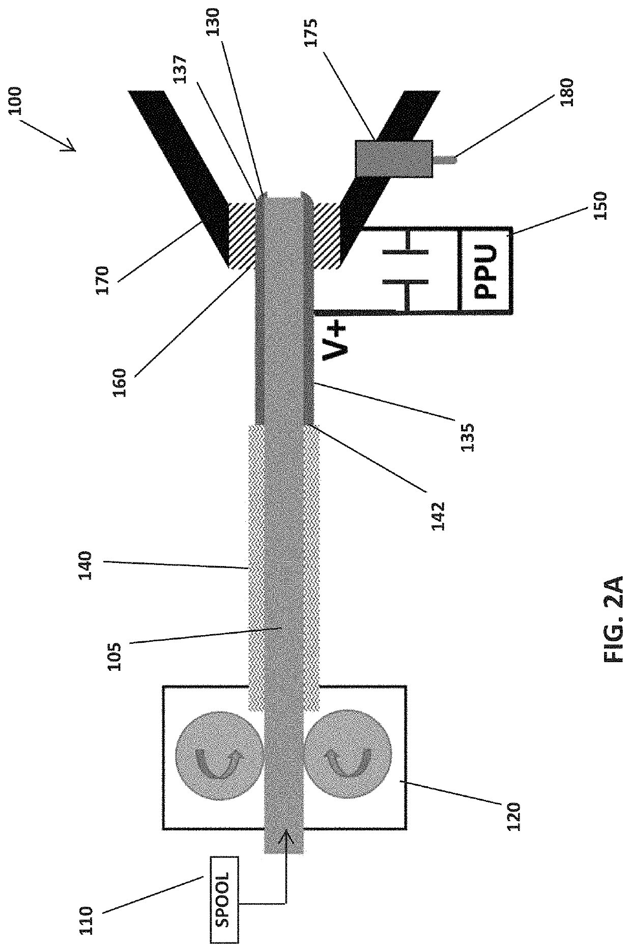
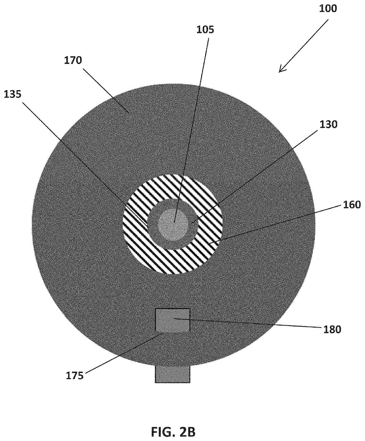
[0053]A schematic of one embodiment of Applicant's Fiber-fed Pulsed Plasma Thruster (FPPT) generally referenced as element 100 is shown in FIGS. 2A and 28. The thruster 100 replaces the spring-fed state of the art Teflon feed system with a fiber feed system, which pulls a Teflon fiber 105 from a spool 110. Prior Art PPT feed systems use a spring to push a propellant bar against a stop without ablation rate control, and this embodiment of the FPPT employs a pulsed stepper motor 120 to drive the fiber 105 against a stop 130 at the tip of a centered anode 135. This system retains a fixed anode / propellant geometry as propellant is consumed. Because of the feed stop 130, it may be necessary to incorporate a slip clutch in the drive mechanism, or to monitor step motor current for a stall. A stall condition will initiate a pause in the feed command, followed by a resumption in feed after an empirically-determined number of pulses.

[0054]In greater detail of FIGS. 2A and 2B, the Teflon fiber...


PUM


Abstract

A Fiber-fed Pulsed Plasma Thruster (FPPT) utilizes a motor to feed PTFE fiber to its discharge region, enabling high PPT propellant throughput and variable exposed fuel area. A highly parallel ceramic capacitor bank lowers system specific mass. Impulse bits (I-bits) from 0.057-0.241 mN-s have been measured on a thrust stand with a specific impulse (Isp) of 900-2400 s, representing an enhancement from state-of-the-art PPT technology. A 1 U (10 cm×10 cm×10 cm, or 1 liter) volume FPPT thruster package will provide 2900-7700 N-s total impulse, enabling 0.6-1.6 km / s delta-V for a 5 kg CubeSat. A 1 U design variation with 590 g propellant enables as much as ˜10,000 N-s and a delta-V of 2 km / s for a 5 kg CubeSat. Increasing the form factor to 2U increases propellant mass to 1.4 kg and delta-V to 10.7 km / s for an 8 kg CubeSat.

Description

CROSS-REFERENCE TO RELATED APPLICATIONS[0001]The present invention in a Continuation in Part of U.S. application Ser. No. 16 / 436,149 filed Jun. 10, 2019, which claims priority to U.S. Provisional Application 62 / 684,275 filed Jun. 13, 2018, both of which are hereby incorporated in their entirety by reference.STATEMENT OF GOVERNMENT SUPPORT[0002]This invention was made with government support under NNX17CP36P and 80NSSC18C0063 awarded by NASA. The Government has certain rights in the invention.BACKGROUND OF THE INVENTION[0003]While classic pulsed plasma thruster (hereinafter “PPT’) propulsion system technology is mature, it has historically been limited by its high mass and small propellant load to precision pointing and small delta-V applications. The PPT has a technology readiness level (TRL) of 9, having flown on several spacecraft beginning with the Soviet Zond 2 mission in 1964, accumulating over 30 thruster years in space through 1991. The LES 8 / 9 PPT was not flown but demonstra...

Claims


Application Information

Patent Timeline
Patent Type & Authority Patents(United States)
IPC IPC(8): F03H1/00B64G1/40H05H1/14H05H1/54
CPCF03H1/0087F03H1/0012B64G1/405F03H1/0031F03H1/0043H05H1/14H05H1/54B64G1/244B64G1/26
Inventor WOODRUFF, CURTISKING, DARRENBURTON, RODNEYCARROLL, DAVID L.
Owner CU AEROSPACE
Why Eureka
Try Eureka