
Tsunami detection system

a detection system and tsunami technology, applied in the field of tsunami detection, can solve the problems of difficult detection and a greater false alarm rate of dart point measurements

Inactive Publication Date: 2012-10-09
THE UNITED STATES OF AMERICA AS REPRESENTED BY THE SECRETARY OF THE NAVY
View PDF9 Cites 10 Cited by
  • Summary
  • Abstract
  • Description
  • Claims
  • Application Information

AI Technical Summary

Benefits of technology

[0009]It is a general purpose and object of the present invention to provide a tsunami detection system that can detect very long wavelengths in ocean waves in real time and can distinguish shallow water waves from wind generated waves having much smaller wavelengths.

Problems solved by technology

Although tsunami waves contain tremendous energy, their distributed nature (e.g., very long periods and wavelengths) make detection difficult.
A satellite radar detection of the tsunami wave created by the 2004 Indian Ocean earthquake was made hours after the tsunami wave originated and occurred far too late to provide any practical warning of the event.
However, given the long tsunami wavelengths, the DART point measurements will have a greater false alarm rate than a distributed measurement.

Method used


Image

  • Tsunami detection system
  • Tsunami detection system
  • Tsunami detection system

Examples


Embodiment Construction

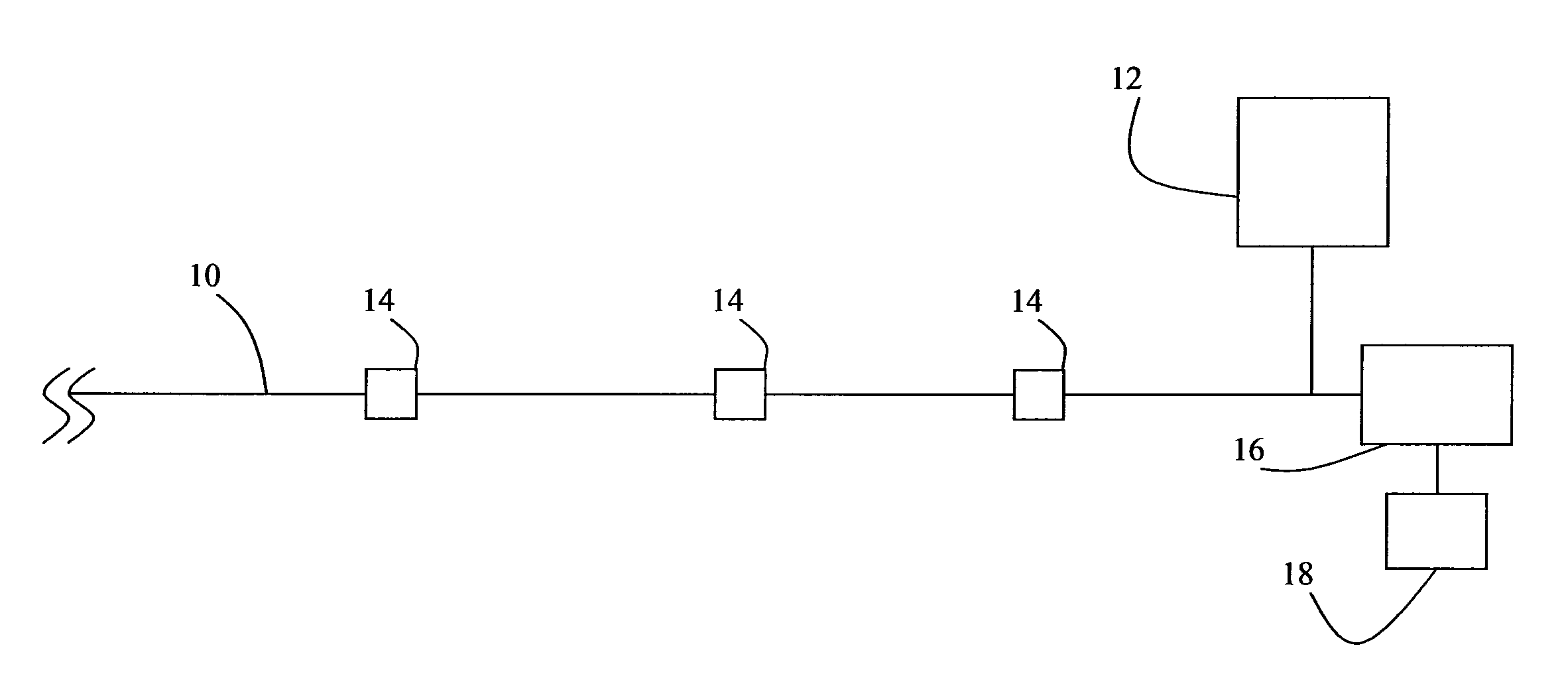
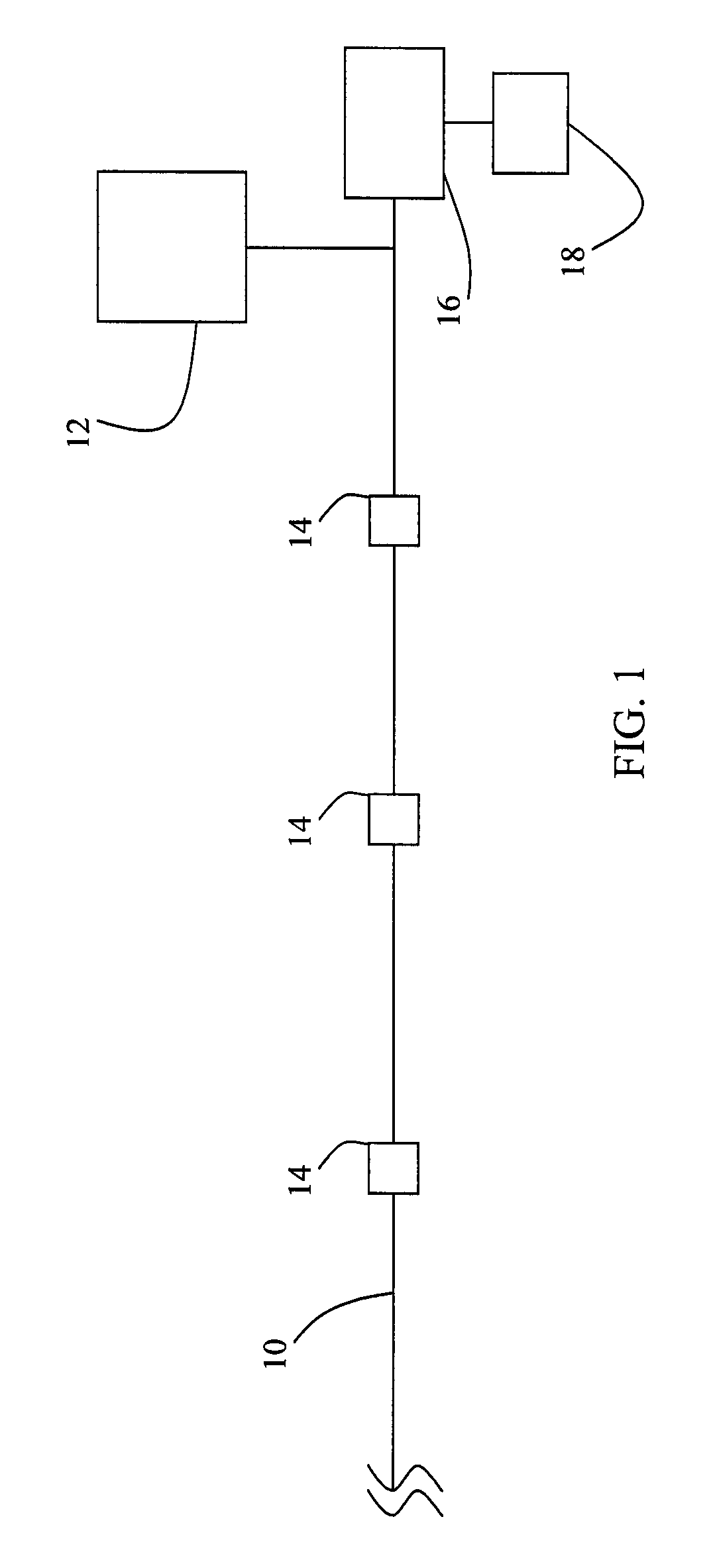
[0017]Referring to FIG. 1, there is illustrated the components of the tsunami wave detection system of the present invention. A telecommunications grade optical fiber cable 10 is spanned across an ocean for use as a pressure sensor. In alternate embodiments more then one optical fiber cable 10 is employed. In a preferred embodiment, the length of the cable 10 is at least 1000 kilometers in length. A laser 12 is connected to the optical fiber cable to generate an optical signal across the optical fiber cable 10. Optical repeaters 14 are integrated into the cable 10 at predetermined distances to overcome losses in the optical signal due to attenuation by the optical fiber. The optical fiber cable 10 is connected to a digital signal processor 16 that will perform optical time delay reflectometry on the optical signal based on the Rayleigh scattering effect. In a preferred embodiment, the digital signal processor 16 is a programmable computer data processing system. State of the art opt...


PUM


Abstract

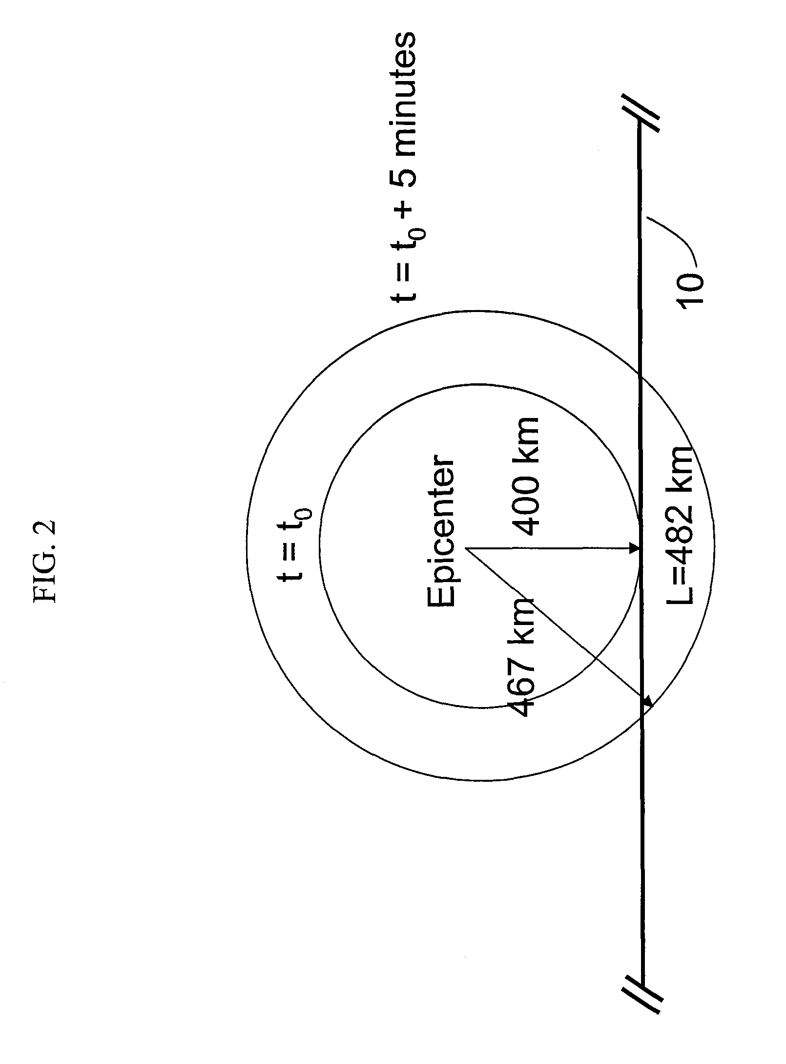
The invention as disclosed is a system for real time detection of tsunami waves. A tsunami is considered a “shallow water wave”, having a large wavelength compared to the ocean depth. A tsunami can have wavelengths ranging from 100 to 500 km, and amplitudes up to 60 cm (i.e., a pressure signal of up to 1 psi). At least one telecommunications grade optical fiber cable fitted with repeaters spanning the length of an ocean, a laser and a signal processor are used to measure pressure signals over spatial cells as small as 0.5 meters in width based on Rayleigh scattering effects and employing optical time delay reflectometry. The tsunami pressure signals are extracted from the pressure signals generated by wind-generated water waves (having much shorter wavelengths) through signal processing to distinguish between the substantial differences in wavelength, period and propagation speed.

Description

STATEMENT OF GOVERNMENT INTEREST[0001]The invention described herein may be manufactured and used by or for the Government of the United States of America for governmental purposes without the payment of any royalties thereon or therefore.CROSS REFERENCE TO OTHER PATENT APPLICATIONS[0002]None.BACKGROUND OF THE INVENTION[0003](1) Field of the Invention[0004]The present invention is directed to tsunami detection. In particular, the present invention is directed to a system that can reduce the amount of time it takes to detect a tsunami by an order of magnitude by using an underwater fiber optic cable as a pressure sensor.[0005](2) Description of the Prior Art[0006]Although tsunami waves contain tremendous energy, their distributed nature (e.g., very long periods and wavelengths) make detection difficult. A satellite radar detection of the tsunami wave created by the 2004 Indian Ocean earthquake was made hours after the tsunami wave originated and occurred far too late to provide any p...

Claims


Application Information

Patent Timeline
Patent Type & Authority Patents(United States)
IPC IPC(8): G08B21/00G02B6/00
CPCG08B21/10G02B6/506Y02A50/00
Inventor RUFFA, ANTHONY A.ERWIN, RICHARD A.BLACKMON, FLETCHER A.
Owner THE UNITED STATES OF AMERICA AS REPRESENTED BY THE SECRETARY OF THE NAVY
Learn More