
On-chip seed generation using boolean functions for LFSR re-seeding based logic BIST techniques for low cost field testability

a logic bist and re-seeding technology, applied in the field of built-in self-test systems, can solve the problems of low test coverage, difficult to test for all defect models at time-zero manufacturing tests, and improper conformance, and achieve simple arithmetic functions, reduce the area required for seed generation, and improve the effect of test coverag

Active Publication Date: 2012-10-09
TEXAS INSTR INC
View PDF13 Cites 16 Cited by
  • Summary
  • Abstract
  • Description
  • Claims
  • Application Information

AI Technical Summary

Benefits of technology

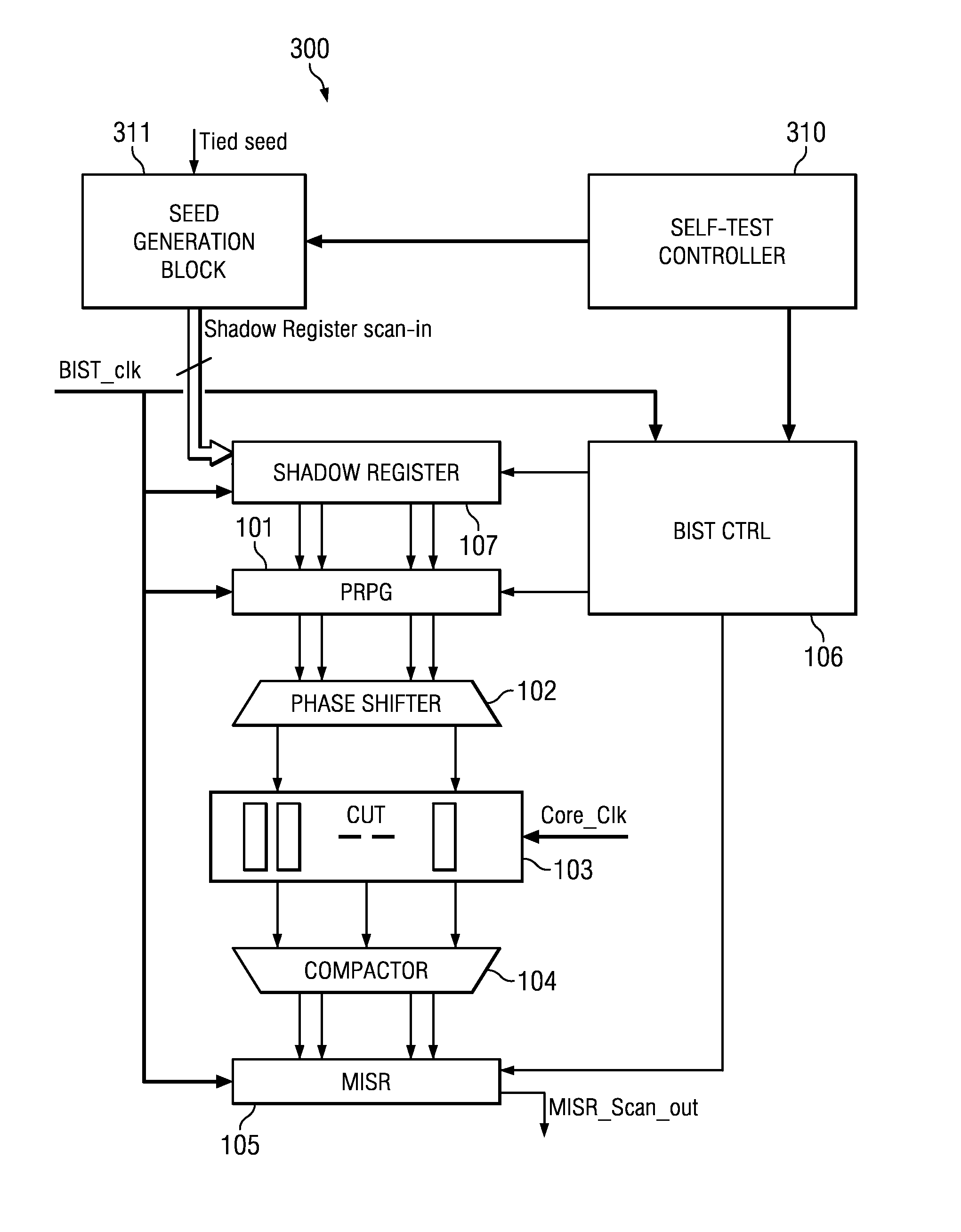
[0011]This invention generates the desired random seed patterns using simple, low-area overhead digital circuitry on-chip. This circuit is implemented as an FSM (finite state machine) whose states are the seeds, wherein Seednext=Function(Seedpresent). Simple arithmetic functions amenable for implementation via simple FSMs are used. This contrasts the prior art approach of storing the seeds in an on-chip memory. In one example implementation, the invention reduces the area required for seed generation from 12K gate equivalents to just 400 gates.
[0012]This invention has five advantages. First, it obtains high test coverage during field self-test as compared to conventional logic BIST. Second, this invention can be used for high speed production testing to cover both stuck-at faults using slow speed clocks and delay faults using at-speed internal PLL based clocks, without dependence on the external tester infrastructure and slow tester communication channels. This potentially improves test quality as well saves test time. Third, the coverage obtained in the field is no longer restricted by the available on-chip memory or the available system level interface for seed transfer from external memory into the CUT. Fourth, the CUT design for test (DFT) architecture can be made independent of the tester architecture with respect to the number of tester channels available for re-seeding or the tester channel and device I / O shift speeds. In fact, the CUT can now be tested in the fastest possible way. Fifth, this invention provides a huge reduction in chip area in comparison with storing seeds on-chip or off-chip because these seeds are now generated using an FSM.

Problems solved by technology

Second, the user may need to check the operating parameters of the device during its use for conformance to specifications.
This conformance may be improper due to design variability in deep sub-micron technologies.
Third, it is increasingly difficult to test for all defect models at time-zero manufacturing tests.
This limited set of care bits results in relatively low test coverage.
Field tests using these traditional logic BIST techniques thus generally suffer from either low coverage or large overhead from the required on-chip memory for seed storage.

Method used


Image

  • On-chip seed generation using boolean functions for LFSR re-seeding based logic BIST techniques for low cost field testability
  • On-chip seed generation using boolean functions for LFSR re-seeding based logic BIST techniques for low cost field testability
  • On-chip seed generation using boolean functions for LFSR re-seeding based logic BIST techniques for low cost field testability

Examples


Embodiment Construction

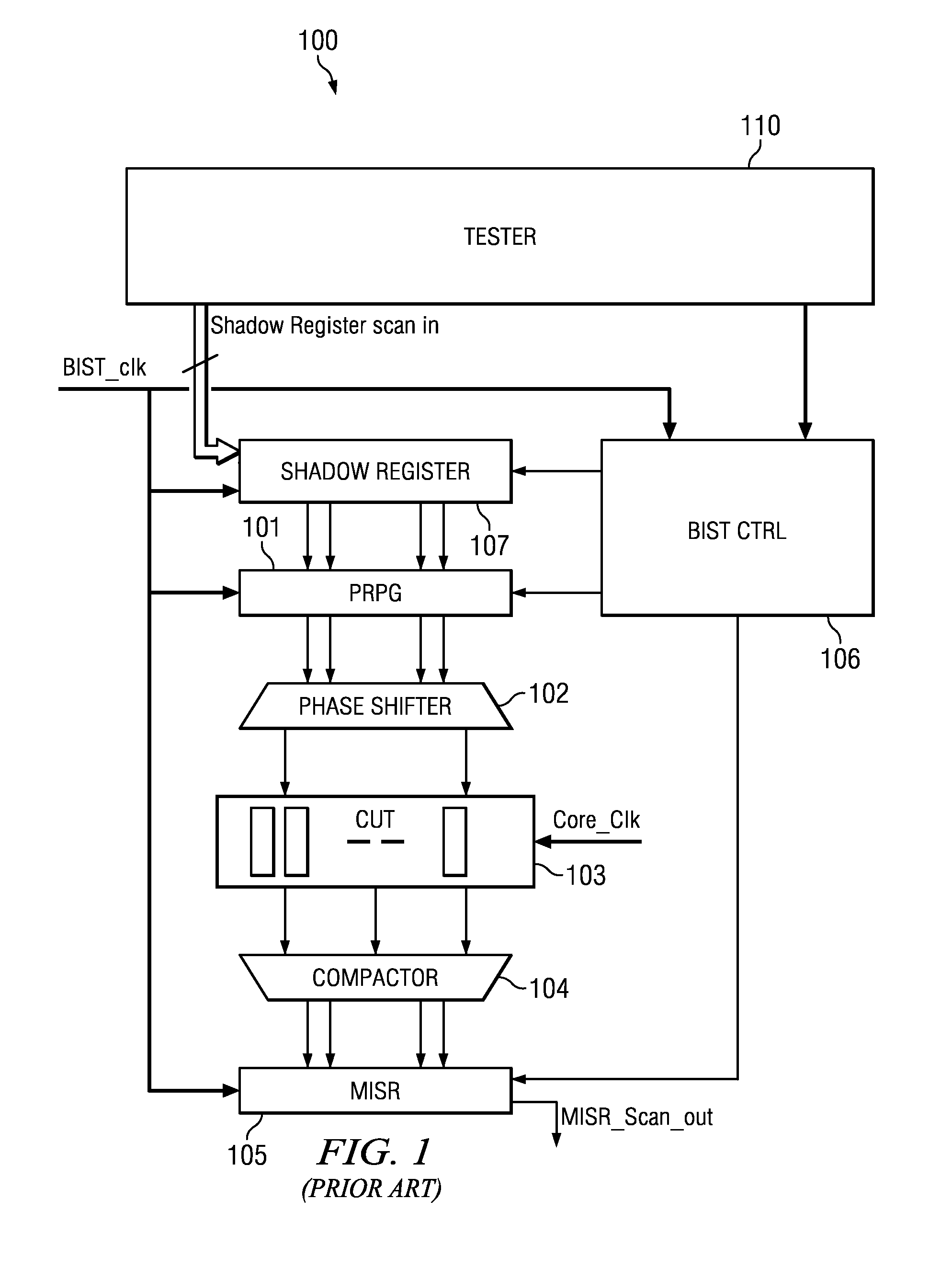
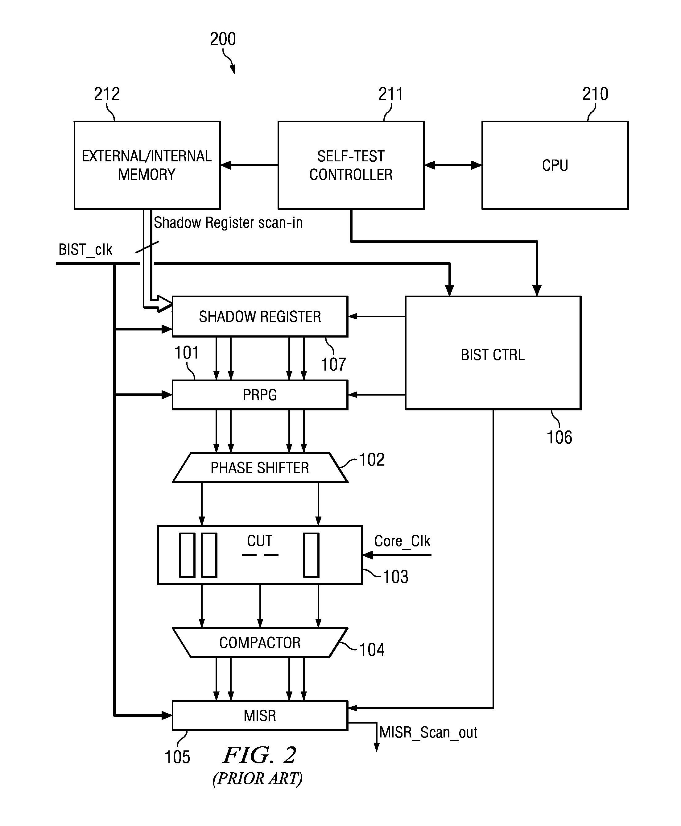
[0022]Field test using logic BIST is commonly employed in safety critical applications. Logic BIST is implemented using LFSRs as pseudo-random pattern generators (PRPG) and a multiple input signature register (MISR) as response compactors. LFSR techniques suffer from low coverage due to pseudo-random patterns. To improve the coverage obtained by traditional LFSR based BIST, re-seeding techniques are used wherein the LFSR is periodically seeded (initialized) to generate a new set of patterns. Re-seeding is effective to obtain high coverage, similar to that obtained using deterministic patterns obtained using ATPG (automatic test pattern generation) techniques. This incurs associated costs of prior seed generation and seed storage on-chip when logic BIST is employed for field test. As a result, field test using traditional logic BIST techniques suffers from either low coverage or has the overhead of requirement of on-chip memory for seed storage. A large number of seeds are often requ...


PUM


Abstract

This invention generates the random seed patterns using simple, low-area overhead digital circuitry on-chip. This circuit is implemented as a finite state machine whose states are the seeds as contrasted to storing the seeds in the prior art. These seeds are used to control pseudo-random pattern generation for built-in self-tests. This invention provides a large reduction in chip area in comparison with storing seeds on-chip or off-chip.

Description

CLAIM OF PRIORITY[0001]This application claims priority under 35 U.S.C. 119(e)(1) to U.S. Provisional Application No. 61 / 154,060 filed Feb. 20, 2009.TECHNICAL FIELD OF THE INVENTION[0002]The technical field of this invention is built-in self-test systems.BACKGROUND OF THE INVENTION[0003]Field tests of integrated circuits are becoming important for three main reasons. First, electronic components are increasingly used in safety critical systems such as automotive and medical electronics. Periodic testing of such safety critical systems is recommended through the lifetime of the device. Second, the user may need to check the operating parameters of the device during its use for conformance to specifications. This conformance may be improper due to design variability in deep sub-micron technologies. In addition various runtime environmental factors may change this conformance. Third, it is increasingly difficult to test for all defect models at time-zero manufacturing tests. Thus syste...

Claims


Application Information

Patent Timeline
Patent Type & Authority Patents(United States)
IPC IPC(8): G01R31/28
CPCG01R31/318385
Inventor GANGASANI, SWATHIALAMPALLY, SRINIVASULUDIVAKARAN, DIVYAPAREKHJI, RUBIN AJITDUTTA, AMIT KUMARRAVI, SRIVATHS
Owner TEXAS INSTR INC
Learn More