Measurement apparatus and measurement method

a measurement apparatus and measurement method technology, applied in the direction of fluid pressure measurement by mechanical elements, vibration measurement in solids, optical radiation measurement, etc., can solve the problems of deterioration of resolution, unfavorable aot measurement, and inability to converge quickly,

Inactive Publication Date: 2012-10-16
CANON KK
View PDF11 Cites 27 Cited by
  • Summary
  • Abstract
  • Description
  • Claims
  • Application Information

AI Technical Summary

Benefits of technology

[0007]The present invention provides a measurement apparatus and a measurement method which can more precisely measure a spectroscopic characteristic of a test object by utilizing AOT and DOT than a single use of AOT.

Problems solved by technology

JP 2005-331292 assumes the internal distribution of the spectroscopic characteristic and employs an algorithm that is used to modify or reconstruct the assumption in accordance with the measurement result, but the calculation of the internal distribution is complex, an enormous and time-consuming process, and unlikely to converge quickly to the optimal solution.
Since the photodetector cannot detect the light unless the light intensity is higher than a threshold, the light intensity becomes too small for AOT measurement as a distance of the test region from the surface of the test object increases.
The increased surface area of the focused ultrasonic waves in AOT can overcome the light intensity deficiency, but will result in a deterioration of the resolution.

Method used


Image

  • Measurement apparatus and measurement method
  • Measurement apparatus and measurement method
  • Measurement apparatus and measurement method

Examples


first embodiment

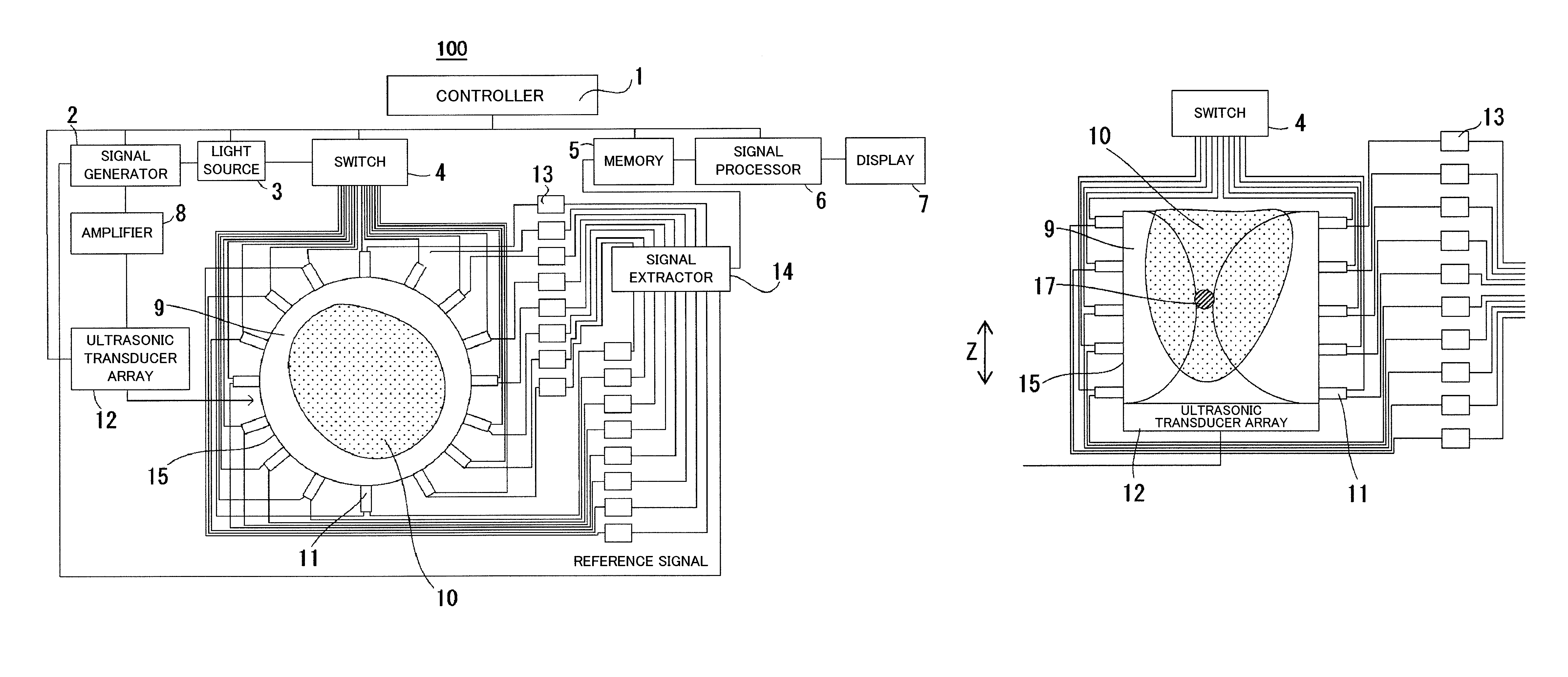
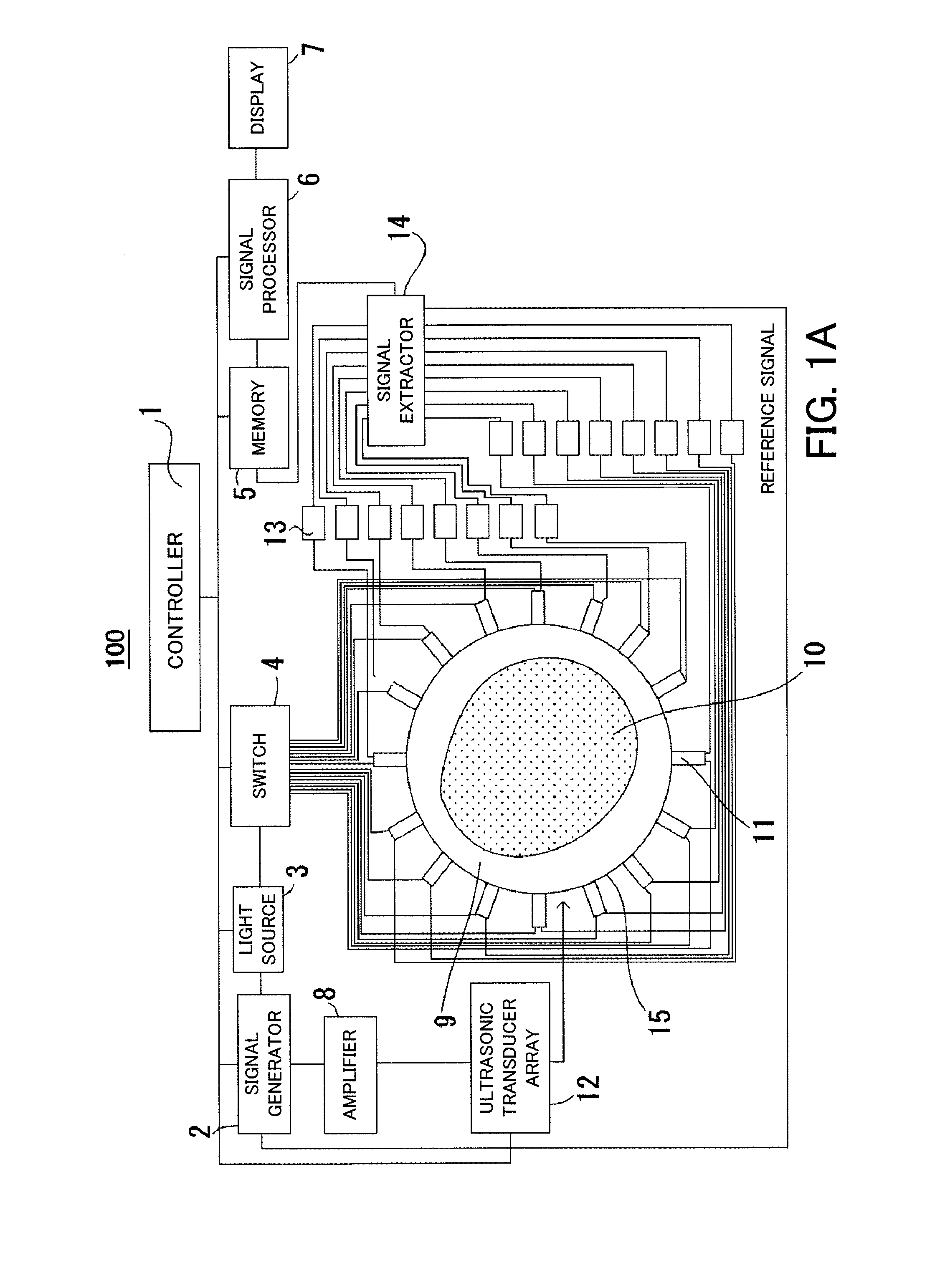
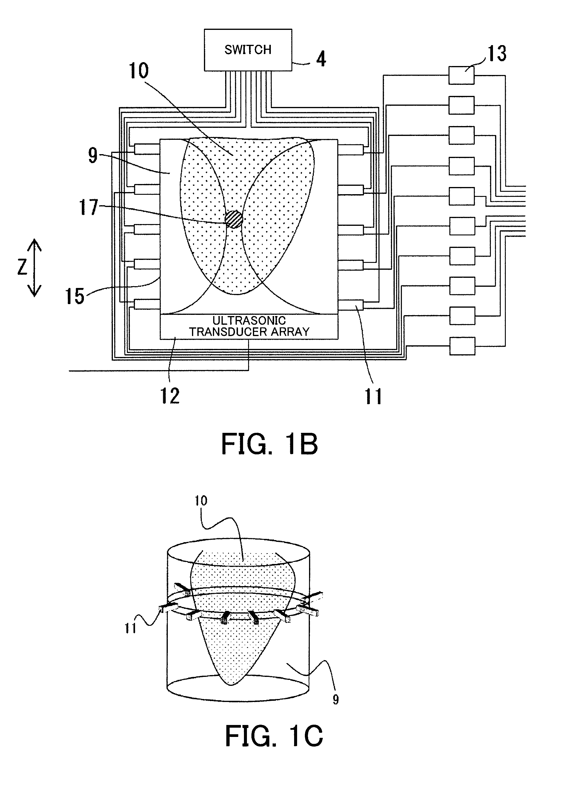
[0022]FIGS. 1A-1C are block diagrams of a measurement apparatus 100 according to a first embodiment. The measurement apparatus 100 measures a spectroscopic characteristic in a tissue of a test object 10, such as a breast, by utilizing both AOT and DOT. The measurement apparatus 100 includes a controller 1, a signal generator 2, a light source 3, a switch 4, a memory 5, a signal processor 6, a display 7, an amplifier 8, a plurality of fibers 11, an ultrasonic transducer array 12, a plurality of photodetectors 13, a signal extractor 14, and a measurement container 15. FIG. 1A is a sectional view of the measurement container 15 that houses the test object 10, FIG. 1B is its side view, and FIG. 1C is its perspective view.

[0023]The measurement apparatus 100 includes a first measurement unit and a second measurement unit. The controller 1 calculates at least one of a scattering characteristic and an absorption characteristic of the test region set in the test object 10 by utilizing one of...

second embodiment

[0099]As described above, the measurement size of the first measurement can be estimated to about 10% of the optical path length once the test object 10 is determined, and thus the second embodiment simplifies the flow of FIG. 5 by eliminating the loop used to determine the mesh size δ1(x, y, z). The estimation can be made by utilizing the size of the test object 10, and the average absorption coefficient and scattering coefficient in the test object 10. The mean absorption coefficient and scattering coefficient can be calculated, for example, from the diffusion equation or Monte Carlo simulation utilizing the light intensity detected in the first measurement unit. The measurement apparatus of this embodiment can use the measurement apparatus 100 shown in FIG. 1 as it is.

[0100]FIG. 9 is a flowchart for explaining the measurement method executed by the controller 1 according to this embodiment. In FIG. 9, “S” denotes “step”. The signal processor 6 rather than the controller 1 may per...


PUM

PropertyMeasurementUnit
refractive indexaaaaaaaaaa
riaaaaaaaaaa
Φ(riaaaaaaaaaa

Abstract

A measurement apparatus includes a DOT measurement unit, an AOT measurement unit, and a controller configured to calculate at least one of an absorption characteristic and a scattering characteristic of a test region set in an test object by utilizing one of the DOT measurement unit and the AOT measurement unit, whichever one has the smaller measurement size.

Description

BACKGROUND OF THE INVENTION[0001]1. Field of the Invention[0002]The present invention relates to a measurement apparatus and a measurement method.[0003]2. Description of the Related Art[0004]Diffused optical tomography (“DOT”) and acousto-optical tomography (“AOT”) are known techniques for measuring a spectroscopic characteristic of a biological tissue. The spectroscopic (or attenuation) characteristic contains an absorption (spectroscopic) characteristic and a scattering (spectroscopic) characteristic, and at least one of the absorption characteristic and the scattering characteristic (which will be also referred to as an “absorption-scattering characteristic” hereinafter) is necessary to measure the biological tissue with a high resolution.[0005]DOT introduces near-infrared light to a test object and detects diffused light, as described in Japanese Patent Laid-Open No. (“JP”)2005-331292. AOT irradiates coherent light and focused ultrasonic waves into the test object, and utilizes ...

Claims


Application Information

Patent Timeline
Patent Type & Authority Patents(United States)
IPC IPC(8): G01N21/00A61B8/00A61B10/00G01N21/17G01N29/00
CPCA61B5/0073A61B5/0091A61B5/0097A61B5/4312G01N21/4795G01N29/0672G01N29/2418
Inventor YOSHIDA, HIROFUMI
Owner CANON KK
Why Eureka
Try Eureka