
UV-VIS-IR imaging optical systems

a technology of optical systems and uv-vis, applied in the field of broadband imaging optics, can solve the problem of rare to find designs that are truly apochromatic, and achieve the effect of high quality

Inactive Publication Date: 2012-10-16
CALDWELL JAMES BRIAN
View PDF33 Cites 4 Cited by
  • Summary
  • Abstract
  • Description
  • Claims
  • Application Information

AI Technical Summary

Benefits of technology

[0014]The UV transparency constraint puts most high index glasses, especially the flint glasses with high dispersion, off-limits since these glasses have high UV absorption, especially in the 315 nm-320 nm region. Consider for example the Ohara glass PBM18Y, which has an index nd of 1.59551 and an Abbe number of 38.77. The Abbe number is defined as (nd−1) / (nF−nC), where nd, nF, and nC are the refractive index values at wavelengths of 587.5618 nm, 486.1327 nm, and 656.2725 nm, respectively. PMB18Y is one of the so-called “I-line” glasses that are specially designed and manufactured to give good UV transmission, especially down to the i-line wavelength of 365.0146 nm. Nonetheless, PBM18Y has an internal transmission of only about 22% through a 10 mm thick sample at a wavelength of 320 nm, and at 310 nm the transmission of PBM18Y drops to nearly zero. Other glasses with similar Abbe number that are not in the I-line class have essentially zero transmission in the 310 nm-320 nm range. Thus, it turns out that virtually all glasses having an Abbe number less than 40 are essentially useless for lenses operating in the 315 nm-1100 nm spectrum. The same is true for glasses having an index of refraction nd greater than 1.8. An exception would be the case where the lens elements are very small, such as in microscope objectives. Here, the small size of the lens elements means that they can be made very thin, thus improving their UV transmission.

Problems solved by technology

But even in these cases, it is rare to find designs that are truly apochromatic, i.e., in which three distinct wavelengths are brought to a common focus.

Method used


Image

  • UV-VIS-IR imaging optical systems
  • UV-VIS-IR imaging optical systems
  • UV-VIS-IR imaging optical systems

Examples


example 1

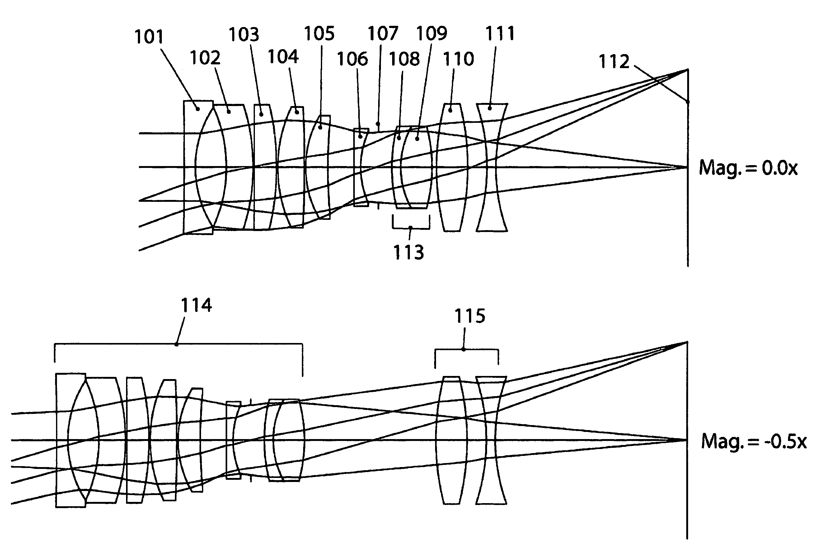
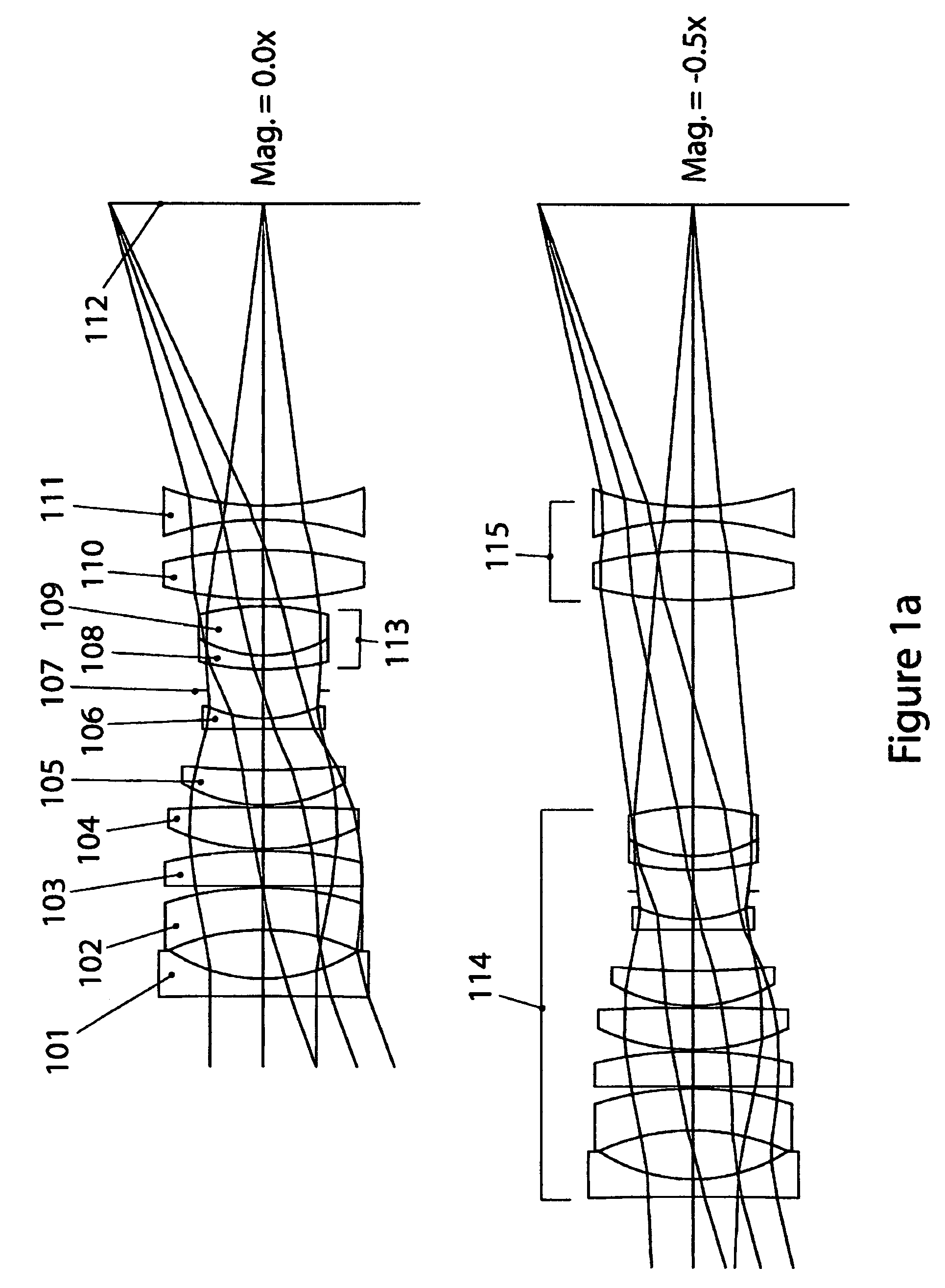
[0060]Example 1, which is a 60 mm focal length macro-focusing photographic objective for 35 mm format, is illustrated in FIG. 1a, which shows cross-sectional layouts at magnifications of 0 and −0.5×. Elements 101, 103, 104, 105, and 109 are made from CaF2; elements 102, 108, 110 and 111 are made from fused silica (SiO2); and element 106 is made from Ohara S-LAL18. Element 107 is the aperture stop and 112 is the image plane. This design has a very high internal transmission throughout the 315 nm-1100 nm waveband because there is just a single thin element (106) that is not CaF2 or fused silica. The addition of a negative-powered S-LAL18 element 106 enables the apochromatic color correction to be far superior in the near infrared to apochromats made solely from CaF2 and SiO2.

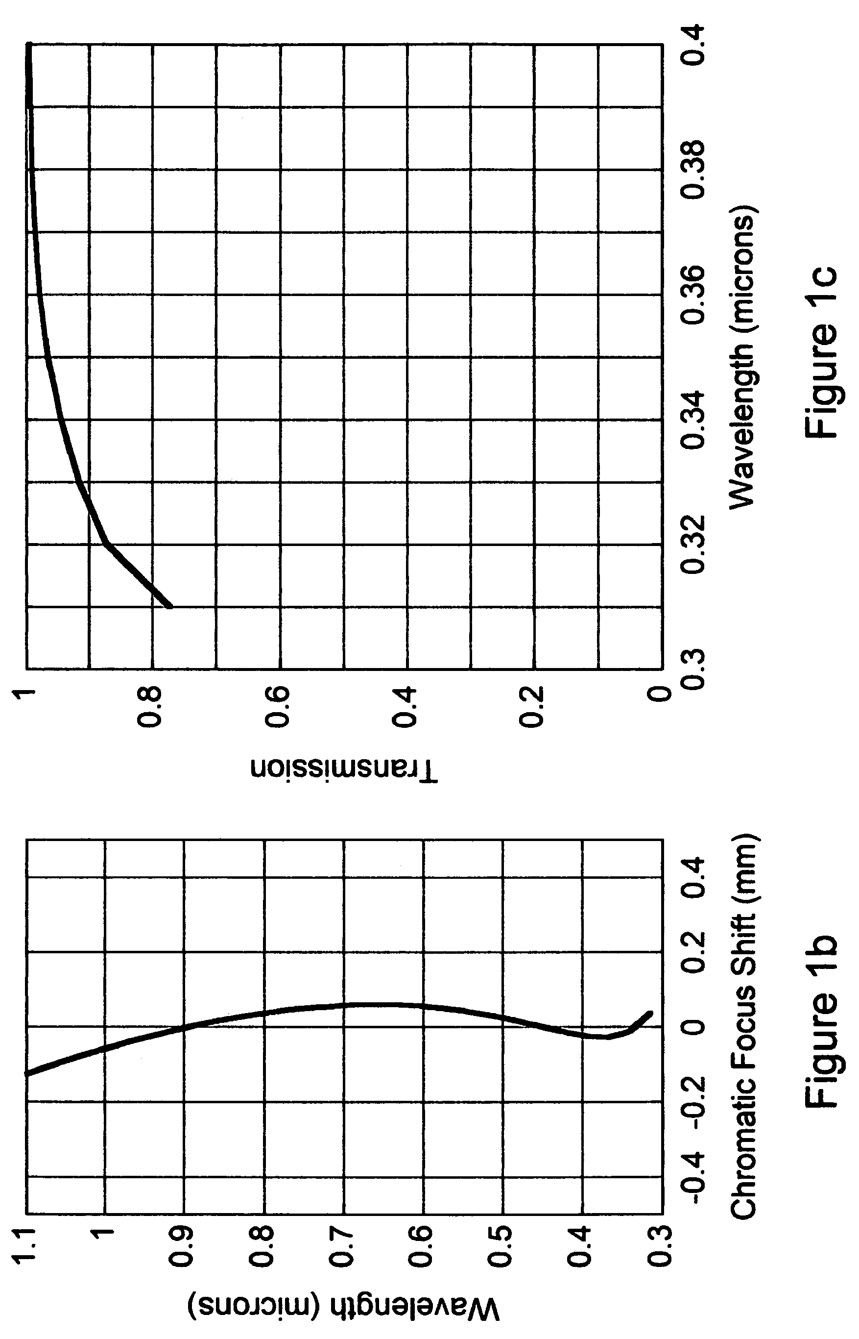
[0061]Example 1 is composed from just three different optical materials, however despite this simplicity it has the combination of both good optical correction and good transparency over the entire 315 nm-1100 nm ...

example 2

[0064]Example 2, which is a 35 mm focal length wide-angle photographic objective for 35 mm format, is illustrated in FIG. 2a, which shows cross-sectional layouts at magnifications of 0 and −0.25×. Elements 206, 211 and 212 are made from CaF2; elements 202 and 204 are made from Ohara S-FPL51; elements 203, 205, 207 and 213 are made from Ohara S-FSL5; element 201 is made from Ohara S-BAL42; and element 210 is made from Ohara S-LAL14. Element 209 is the aperture stop and 214 is the image plane. In this design, S-FPL51 has been used as a substitute for CaF2 in the larger elements 202 and 204 in order to reduce costs. However, this reduces the transmission at 315 nm. S-LAL14 and S-BAL42 are used as matching flints. Separating the design into two independently moving groups 216 and 217 eliminates variation of lateral chromatic aberration and astigmatism during focusing.

[0065]Element 208 is a 5 mm thick filter with plane parallel surfaces made of S-BSL7. It is anticipated that in ordinary ...

example 3

[0069]Example 3, which is a 24 mm focal length wide-angle photographic objective for 35 mm format, is illustrated in FIG. 3a, which shows cross-sectional layouts at magnifications of 0 and −0.15×. Elements 301, 305 and 314 are made from fused silica (SiO2); elements 303, 304, 306, 308, 312 and 313 are made from CaF2; element 302 is made from Ohara S-FPL51Y; element 309 is made from Ohara S-FPL51; element 307 is made from Ohara S-BAL42; and element 311 is made from Ohara S-LAL18. Element 310 is the aperture stop and 315 is the image plane. Example 3 bears a resemblance to Example 2, but in Example 3 there is more extensive use of CaF2, SiO2 and S-FPL51Y. As a result, Example 3 has a significantly higher transmission at 315 nm than Example 2. Apochromatic performance has been achieved by pairing CaF2 and S-FPL51Y with S-LAL18 and S-BAL42. Separating the design into two independently moving groups 317 and 318 eliminates variation of lateral chromatic aberration and astigmatism during f...


PUM


Abstract

Imaging optical systems having good transmission and that are well corrected over the full 315 nm-1100 nm ultraviolet-visible-infrared (UV-VIS-IR) wavelength band are disclosed. A wide variety of apochromatic and superachromatic design examples are presented. The imaging optical systems have a broad range of applications in fields where large-bandwidth imaging is called for, including but not limited to forensics, crime scene documentation, art conservation, forgery detection, medicine, scientific research, remote sensing, and fine art photography.

Description

CLAIM OF PRIORITY[0001]This application claims priority under 35 USC §119(e) from U.S. Provisional Patent Application Ser. No. 60 / 961,329 filed on Jul. 20, 2007, which patent application is incorporated by reference herein.FIELD OF THE INVENTION[0002]The present invention relates to the field of broadband imaging optics, and more specifically relates to optical systems that have good transmission and are well corrected over a very wide spectrum ranging approximately from 315 nm in the ultraviolet through approximately 1100 nm in the infrared.BACKGROUND ART[0003]Recent advances in silicon-based image detectors have opened up possibilities for photography in a very wide waveband ranging from the deep UV (<200 nm) all the way to about 1100 nm in the near infrared. For many practical photographic purposes the UV portion of this waveband is limited to about 315 nm by atmospheric absorption of sunlight. The spectrum from 315 nm to 400 nm is commonly called the UVA spectrum. So, a very ...

Claims


Application Information

Patent Timeline
Patent Type & Authority Patents(United States)
IPC IPC(8): G02B9/12
CPCG02B13/146G02B15/177
Inventor CALDWELL, JAMES BRIAN
Owner CALDWELL JAMES BRIAN
Learn More