
Self-cleaning foam-dispensing device

Active Publication Date: 2012-10-23
REXAM AIRSPRAY
View PDF12 Cites 9 Cited by
  • Summary
  • Abstract
  • Description
  • Claims
  • Application Information

AI Technical Summary

Benefits of technology

[0010]It is an object of the invention to provide a dispensing device for forming a foam which reduces the quantity of foam remaining behind in the dispensing passage, in particular in the mixing chamber and / or the sieve elements.
[0012]This air which will be dispensed during the second part of the stroke will push / blow the foam which is already present in the dispensing passage forward in the direction of the dispensing opening. As a result, less foam will remain behind in the dispensing passage and thus less foam / liquid will dry up in this dispensing passage.
[0016]A second possibility to prevent the delivery of liquid to the dispensing passage during the second part of the stroke of the operating element is to return the liquid pumped during the second part of the stroke to the container instead of to the dispensing passage, for example by closing the liquid delivery valve to the dispensing passage and opening a second liquid delivery valve which allows the liquid to flow back to the container. The second liquid delivery valve may, for example, be a pressure relief valve which opens as soon as the pumping of liquid further towards the dispensing opening is prevented at the end of the first part of the stroke of the operating element, as a result of which the pressure in the pump chamber of the liquid pump increases.

Problems solved by technology

A drawback of the known dispensing device is that after the foam has been formed and dispensed by the operating element being pressed, a certain amount of foam remains behind in the dispensing passage.
This may be particularly disadvantageous with the sieves in the sieve element, since the dried-up and encrusted liquid may block the sieves and thus render it more difficult to subsequently dispense foam using the dispensing device or may even prevent it.
Another disadvantage of the known dispensing device is that the foam which remains behind in the dispensing passage, for example near the dispensing opening, can drip from the dispensing opening, in particular when the foam turns back into a liquid again.
This problem also occurs with dispensing devices which have been positioned or are operated in such a manner that the dispensing opening is at least partly pointing downwards, for example in a wall dispensing device which is arranged in a fixed position on the wall with the dispensing opening pointing downwards, such as are in use in public toilets.
Such dripping is undesirable, in particular as it is possible that this dripping only occurs some time after the dispensing device has been used, that is when the foam has turned back into liquid.
However, the foam is carried along into the air pump chamber and may there adversely affect the action of the air pump, as has been described above.
Although such foam pumps are referred to as being self-cleaning, they do not achieve the desired result.
In addition, the sucked-back foam and / or the liquid formed from it may dry up in the dispensing device and become encrusted and thus negatively affect the action of the dispensing device.
Liquid which has dried up and become encrusted there may in particular reduce the guidance between the air cylinder and the air piston and thus the action of the air pump.

Method used


Image

  • Self-cleaning foam-dispensing device
  • Self-cleaning foam-dispensing device
  • Self-cleaning foam-dispensing device

Examples


Embodiment Construction

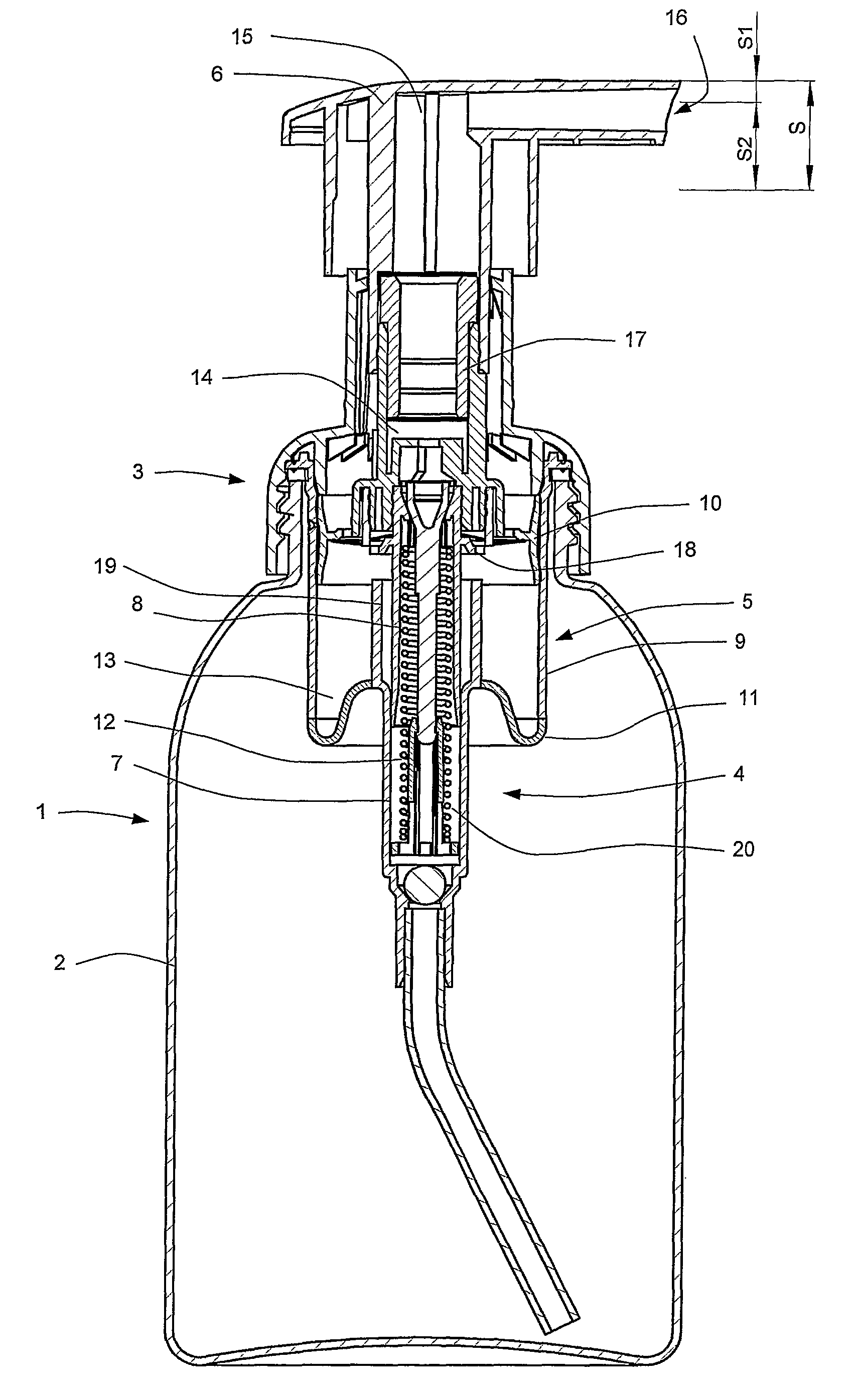
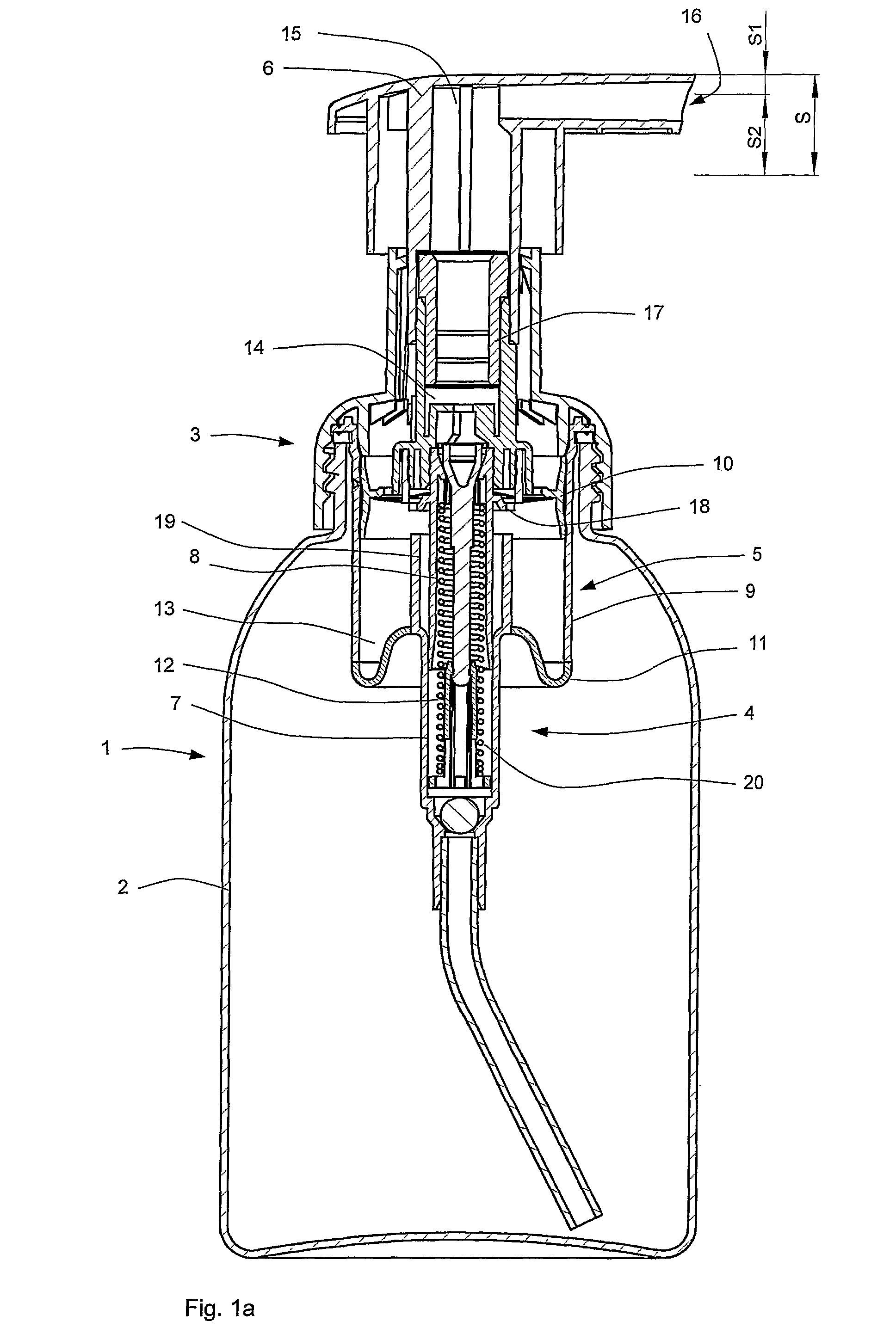
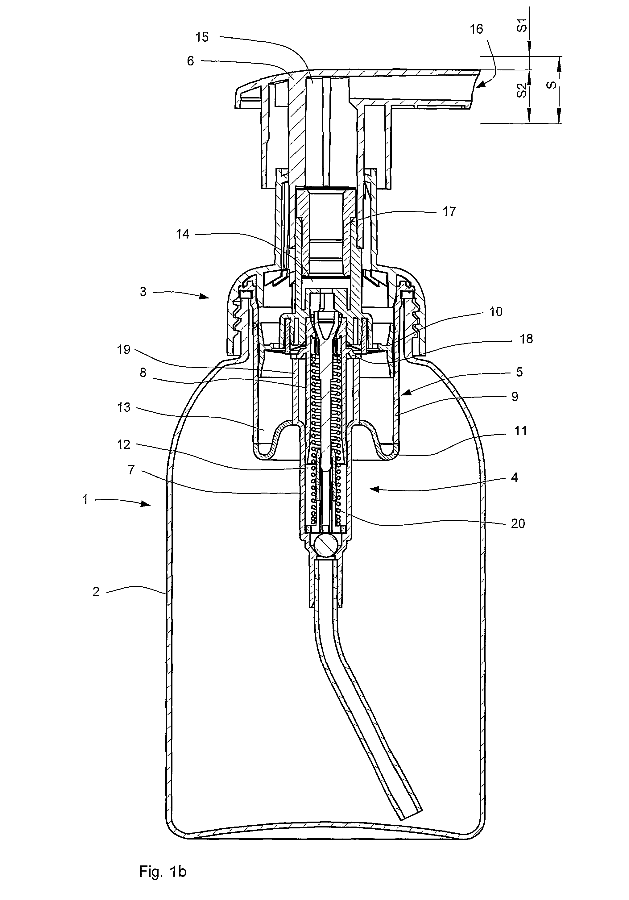
[0027]FIG. 1a shows a dispensing device for dispensing a foam which is denoted overall by reference numeral 1. The dispensing device comprises a container 2 for holding a foamable liquid. The illustrated container 2 is a bottle which has to be aerated in order to prevent it from collapsing due to an underpressure in the container. However, it is also possible to use compressible containers, such as air-tight bags or compressible bottles.

[0028]A pump assembly 3 is fitted on an opening of the container 2. The pump assembly comprises a fitting collar for fitting the pump assembly 3 to the container 2, a liquid pump 4, an air pump 5 and a common operating button 6 which serves as operating element for the liquid pump and the air pump. In an alternative embodiment, the operating element may also be designed as a lever of a so-called trigger pump or a button of a wall-mounted container. The common operating button 6 can perform a stroke S with respect to a fixed part of the pump assembly ...


PUM


Abstract

A foam dispensing device uses a single actuator to actuate two concentric pistons, one for an air chamber and one for a telescopically oriented liquid chamber. In all of the various embodiments the liquid chamber stops its actuation first and can continue to move along with the single actuator and the air chamber continues to dispense air. The air and liquids are dispensed into foaming chamber and then dispensed. The liquid chamber can continue to move because the liquid chamber is attached to the pump system by a deformable connector or some form. This arrangement allows for a foaming device that uses just one actuator that has the ability to dispense foam in the first phase and just air to clear out the nozzle effectively in the second phase.

Description

CROSS-REFERENCE TO RELATED APPLICATIONS[0001]This application is the National Stage of International Application No. PCT / NL2007 / 000035, filed Feb. 6, 2007, which claims the benefit of Netherlands Application No. NL 1031092, filed Feb. 7, 2006, the contents of which is incorporated by reference herein.FIELD OF THE INVENTION[0002]The present invention relates to a dispensing device for dispensing a foam. More particularly, the invention relates to a manually operable dispensing device for dispensing a foam, which comprises a liquid pump and an air pump for pumping a foamable liquid and air, respectively.BACKGROUND OF THE INVENTION[0003]Dispensing devices for dispensing a foam are known per se. U.S. Pat. No. 5,271,530 and U.S. Pat. No. 5,443,569, for example, disclose a dispensing device which comprises a pump assembly for forming a foam. The pump assembly comprises a liquid pump for pumping liquid and an air pump for pumping air to a common dispensing passage. The liquid pump and air ...

Claims


Application Information

Patent Timeline
IPC IPC(8): B67D7/46
CPCB05B7/0037B05B11/3087B05B11/3028B05B11/1028B05B11/1087B05B11/00B05B7/00
Inventor VAN DER HEIJDEN, EDGAR IVO MARIA
Owner REXAM AIRSPRAY
Learn More